34 35
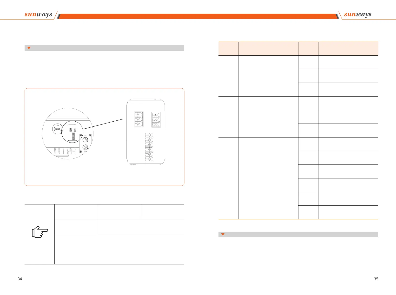
※ 4.7 Meter/RS485/DRED Connection
Figure 4-26
Note
Port 1 Port 2 Port3
Meter Port RS485 Port DRED Port
① This port is available on export limitation & control, RS485 and DRED versions of the
inverter only.
② The Pin connector in inverter Port1 and Port2 may vary from 2Pin to 3pin according to
the shipment version.
Inverter communication ports are located at the behind of the COM2 plate at the bottom
and include RS485 port (used for Meter or Datalogger connection), and DRED port, as
shown in Figure 4-26:
4.7.1 Terminals denition
4 Installation
1 1
1
3
5
2 2
3 3
2
4
6
Port 1 Port 2
Port 3
Dierent versions of the inverter have dierent terminals, which are dened as follows:
Port Function NO. Denition
Port1
① Only Export limitation & control ver-
sion with this port.
② Connect external Meter (with 3CTs)
to activate the Export Limitation & con-
trol function on Sunways STT series
inverter.
1 RS485 A
2 RS485 B
3 PE/NULL
Port 2
① Export limitation & control/RS485/
DRED version with this port.
② ln case of multiple inverters, all the
inverters can be daisy-chained via
RS485 cables.
1 RS485 A
2 RS485 B
3 PE/NULL
Port 3
① Only DRED version with this port.
② DRED means demand response en-
able device. The AS/NZS 4777.2:2015
requires inverters to support demand
response mode (DRM). This function
is for inverters that comply with AS/
NZS4777.2:2015 standard.
③ Sunways inverter is fully compliant
with all DRM. The 6pin connector is
used for DRM connection.
④ Support DRM command: DRMO,
DRM5, DRM6, DRM7, DRMB.
1 COM/DRMO
2 REFGEN
3 DRM4/8
4 DRM3/7
5 DRM2/6
6 DRM1/5
STT series three-phase inverter supports multiple inverters daisy-chain connection to a
data logger via RS485 communication.
Multiple inverters connection diagram as shown in Figure 4-27:
4.7.2 RS485 Communication
4 Installation