Chapter 2: Installation
2-13
1394 CODE
JLED1
JVR2
JPL1
JBR1
JPL2
JPAC1
JWD1
JPI1
JVR1
JBT1
LV33
JSTBY1
T-SGPIO1
C7Z87
Rev. 1.01
BIOS
LICENSE
JTPM1
JPW2
I-SATA1
I-SATA2
I-SATA3
I-SATA4
I-SATA5
I-SATA0
J1394_2
J1394_1
JL1
JHD_AC1
JWOR1
JSPDIF_OUT
JI2C1
JI2C2
JPW1
MAC CODE
BAR CODE
LED1
SP1
FAN3
FAN2
FAN5
FAN1
FAN4
JD1
SLOT5 PCI-E 2.0 X1
SLOT3 PCI-E 2.0 X1
SLOT1 PCI 33MHz
SLOT2 PCI 33MHz
USB 14/15(3.0)
USB12/13(3.0)
USB8/9
USB 2/3
LAN2 LAN1
HDMI/DP
KB/MOUSE
CPU
USB 0/1
AUDIO FP
DIMMB2
HD AUDIO
USB4/5
USB6/7
JF1
Always populate blue sockets first;
Unbuffered ECC/non-ECC DDR3 DIMM required
SLOT4 PCI-E 3.0 X8 (IN X16)
SLOT7 PCI-E 2.0 X1
COM2
COM1
VGA/DVI
USB10/11(3.0)
SLOT6 PCI-E 3.0 X16
T-SGPIO2
A-SATA0
A-SATA1
Intel PCH
BIOS
JSD1
JPME2
DIMMB1
DIMMA1
DIMMA2
Caution: 1) To avoid damaging the motherboard and its components, please do
not use a force greater than 8 lb/inch on each mounting screw during motherboard
installation. 2) Some components are very close to the mounting holes. Please take
precautionary measures to avoid damaging these components when installing the
motherboard to the chassis.
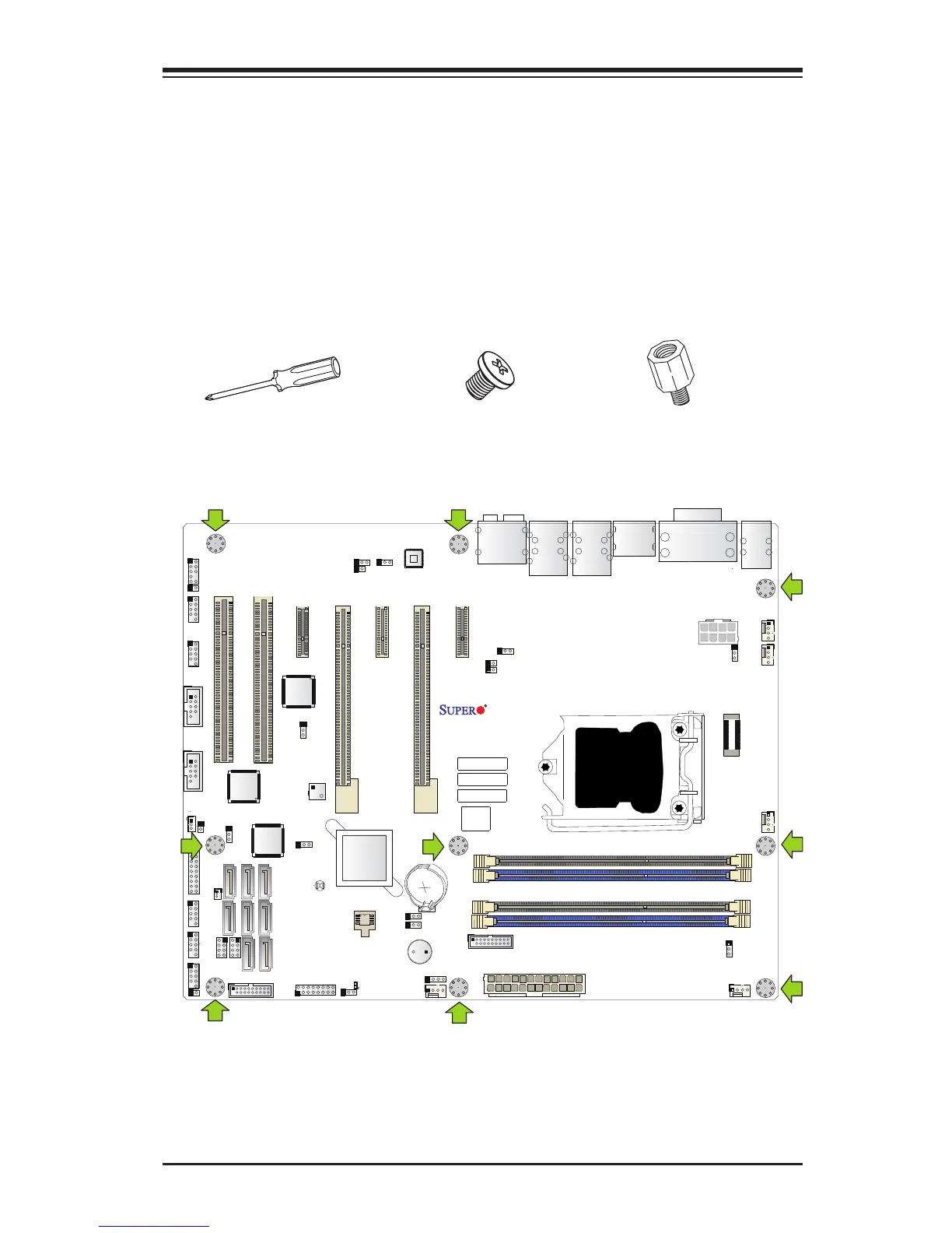
2-5 Motherboard Installation
All motherboards have standard mounting holes to t different types of chassis.
Make sure that the locations of all the mounting holes for both motherboard and
chassis match. Although a chassis may have both plastic and metal mounting fas-
teners, metal ones are highly recommended because they ground the motherboard
to the chassis. Make sure that the metal standoffs click in or are screwed in tightly.
Then use a screwdriver to secure the motherboard onto the motherboard tray.
Tools Needed
Philips Screwdriver
(1)
Standoffs (9)
Only if Needed
Philips Screws (9)
Location of Mounting Holes