Chapter 2: Installation
2-19
1394 CODE
JLED1
JVR2
JPL1
JBR1
JPL2
JPAC1
JWD1
JPI1
JVR1
JBT1
LV33
JSTBY1
T-SGPIO1
C7Z87
Rev. 1.01
BIOS
LICENSE
JTPM1
JPW2
I-SATA1
I-SATA2
I-SATA3
I-SATA4
I-SATA5
I-SATA0
J1394_2
J1394_1
JL1
JHD_AC1
JWOR1
JSPDIF_OUT
JI2C1
JI2C2
JPW1
MAC CODE
BAR CODE
LED1
SP1
FAN3
FAN2
FAN5
FAN1
FAN4
JD1
SLOT5 PCI-E 2.0 X1
SLOT3 PCI-E 2.0 X1
SLOT1 PCI 33MHz
SLOT2 PCI 33MHz
USB 14/15(3.0)
USB12/13(3.0)
USB8/9
USB 2/3
LAN2 LAN1
HDMI/DP
KB/MOUSE
CPU
USB 0/1
AUDIO FP
DIMMB2
HD AUDIO
USB4/5
USB6/7
JF1
Always populate blue sockets first;
Unbuffered ECC/non-ECC DDR3 DIMM required
SLOT4 PCI-E 3.0 X8 (IN X16)
SLOT7 PCI-E 2.0 X1
COM2
COM1
VGA/DVI
USB10/11(3.0)
SLOT6 PCI-E 3.0 X16
T-SGPIO2
A-SATA0
A-SATA1
Intel PCH
BIOS
JSD1
JPME2
DIMMB1
DIMMA1
DIMMA2
C
Front Accessible Audio Header
A 10-pin Audio header is also located on the
motherboard. This header allows you to use
the onboard sound for audio playback. Connect
an audio cable to the audio header to use this
feature. See the table at right for pin denitions
for the header.
10-in Audio
Pin Denitions
Pin# Signal
1 Microphone_Left
2 Audio_Ground
3 Microphone_Right
4 Audio_Detect
5 Line_2_Right
6 Ground
7 Jack_Detect
8 Key
9 Line_2_Left
10 Ground
A
A. Audio Header
B. HDMI
C. Display Port
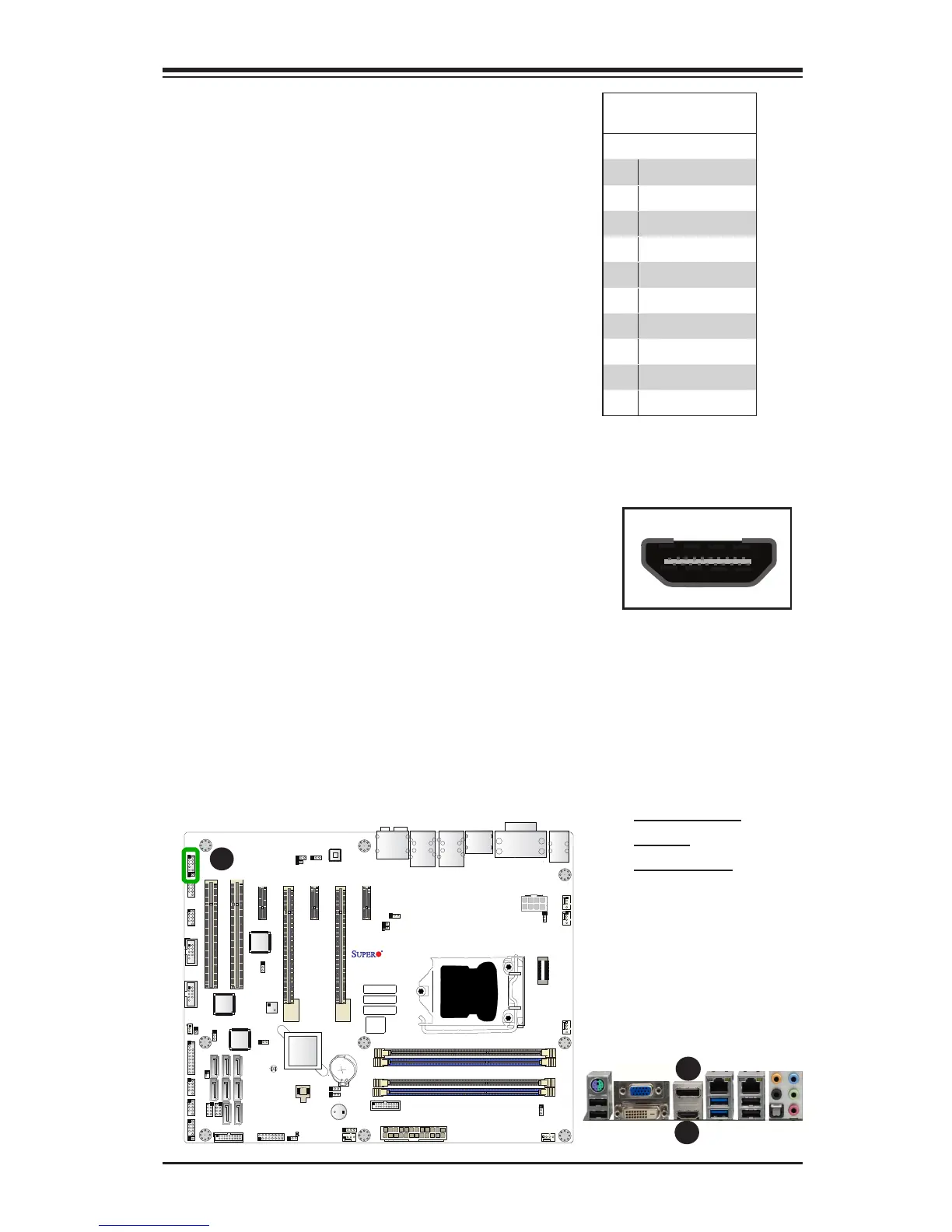
HDMI and Display Port (DP)
Connections
An HDMI (High-Denition Multimedia Inter-
face) and a Display Port are located next to
the VGA port on the I/O backpanel. These
connections are used to display both high
denition video and audio through HDMI/
DP-compatible cables. (Cables are not
included).
B