Chapter 2: Installation
2-27
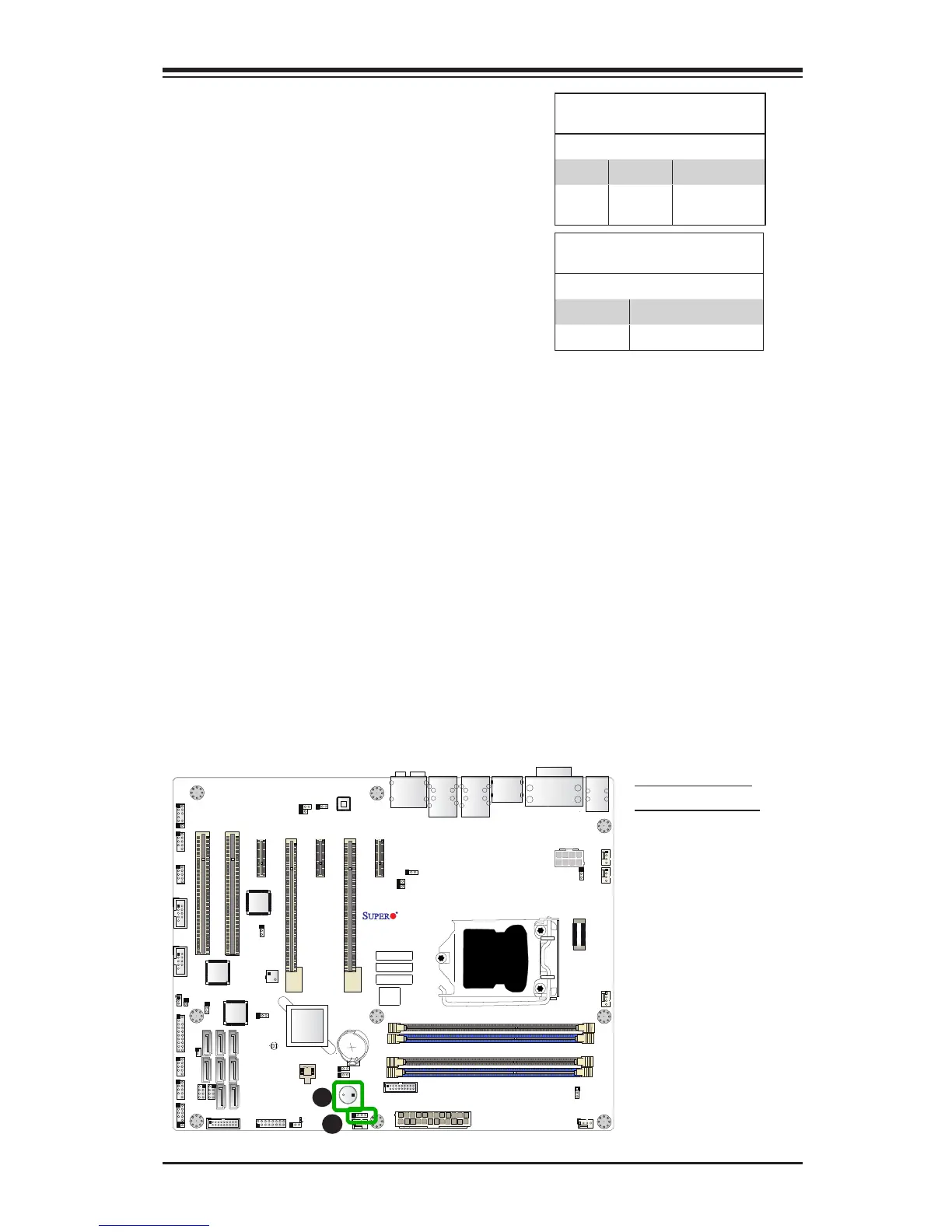
Internal Buzzer (SP1)
The Internal Buzzer (SP1) can be
used to provide audible indications for
various beep codes. See the table on
the right for pin denitions.
A. Internal Buzzer
B. Speaker Header
Internal Buzzer
Pin Denition
Pin# Denitions
Pin 1 Pos. (+) Beep In
Pin 2 Neg. (-) Alarm
Speaker
Speaker (JD1)
On the JD1 header, Pins 3~4 are used
for internal speaker. Close Pins 3~4
with a cap to use the onboard speaker.
If you wish to use an external speaker,
close Pins 1~4 with a cable. See the
table on the right for pin denitions.
Speaker Connector
Pin Denitions
Pin Setting Denition
Pins 3~4 Internal Speaker
Pins1~4 External Speaker
1394 CODE
JLED1
JVR2
JPL1
JBR1
JPL2
JPAC1
JWD1
JPI1
JVR1
JBT1
LV33
JSTBY1
T-SGPIO1
C7Z87
Rev. 1.01
BIOS
LICENSE
JTPM1
JPW2
I-SATA1
I-SATA2
I-SATA3
I-SATA4
I-SATA5
I-SATA0
J1394_2
J1394_1
JL1
JHD_AC1
JWOR1
JSPDIF_OUT
JI2C1
JI2C2
JPW1
MAC CODE
BAR CODE
LED1
SP1
FAN3
FAN2
FAN5
FAN1
FAN4
JD1
SLOT5 PCI-E 2.0 X1
SLOT3 PCI-E 2.0 X1
SLOT1 PCI 33MHz
SLOT2 PCI 33MHz
USB 14/15(3.0)
USB12/13(3.0)
USB8/9
USB 2/3
LAN2 LAN1
HDMI/DP
KB/MOUSE
CPU
USB 0/1
AUDIO FP
DIMMB2
HD AUDIO
USB4/5
USB6/7
JF1
Always populate blue sockets first;
Unbuffered ECC/non-ECC DDR3 DIMM required
SLOT4 PCI-E 3.0 X8 (IN X16)
SLOT7 PCI-E 2.0 X1
COM2
COM1
VGA/DVI
USB10/11(3.0)
SLOT6 PCI-E 3.0 X16
T-SGPIO2
A-SATA0
A-SATA1
Intel PCH
BIOS
JSD1
JPME2
DIMMB1
DIMMA1
DIMMA2
A
B