Release: 1.0a 8 / 24
Supermicro Switch Web GUI Quick Configuration Guide
The Logout link provides a means of signing out of the management web application. It returns to
the login screen requesting a user name and password for login.
2.2.2 Page Top LED Display
This part of the screen displays the port status of the switch. It displays Speed and Link status for
every port. Since the number of ports is different between each of the switches, this displays a
different number of ports for each type of switch.
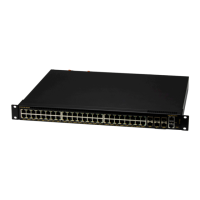
For SSE-G48-TG4, it displays 48 Gigabit Ethernet ports and four 10-Gigabit Extreme Ethernet
ports.
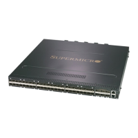
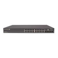
For SSE-G24-TG4, it displays 24 Gigabit Ethernet ports and four 10-Gb Extreme Ethernet ports.
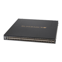
For SSE-X24S, it displays 24 10-Gb Extreme Ethernet ports.
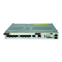
For SBM-GEM-X2C, it displays 16 Gigabit Ethernet ports and three 10-Gb Extreme Ethernet
ports.
For SBM-GEM-X2C+, it displays 22 Gigabit Ethernet ports and three 10-Gb Extreme Ethernet
ports.
For SBM-GEM-X3S+, it displays 24 Gigabit Ethernet ports and three 10-Gb Extreme Ethernet
ports.
For SBM-XEM-X10SM, it displays 24 10-Gb Extreme Ethernet ports and one Gigabit Ethernet
port.
Note:
Ex ports configured as stacking ports will not be displayed in this LED display. The link status of
stacking ports is displayed on the stacking pages.
In stacking, a switch identifier will be displayed on top of this LED display. You can select the
stack member switch of interest in order to view the LED display for that corresponding switch.
2.2.3 Left Side Tree
The Left Side Tree display on the left side of the page provides quick access to configuration
pages. This tree is organized based on the features supported in the switch. The main features
are categorized as follows:
System Management – System based configurations
Layer 2 Management – Layer 2 Protocols including VLAN, RSTP, MSTP …
Layer 3 Management – Layer 3 Protocols including – IP, RIP, OSPF ….

 Loading...