10
SuperServer 1029P-MT/MTR User's Manual
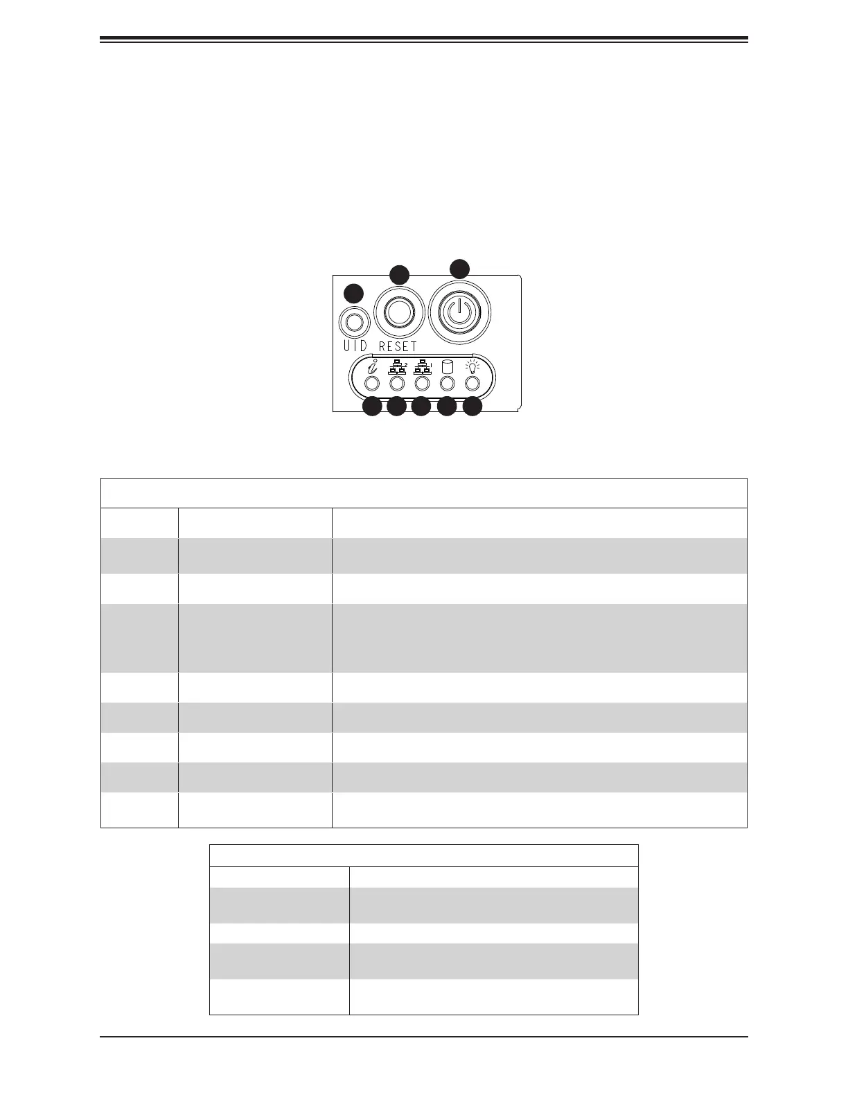
1.4 Server Chassis Features
Control Panel
The switches and LEDs located on the control panel are described below. See Chapter 4 for
details on the control panel connections.
Control Panel Features
Item Feature Description
1 Universal ID LED
Another UID is located on the rear of the chassis.
2 Reset Button The reset button is used to reboot the system.
3 Power Button
The main power button is used to apply or remove power from the power supply
to the server. Turning off system power with this button removes the main power
but maintains standby power. To perform many maintenance tasks, you must
also unplug system before servicing.
4 Information LED See table below for details.
5 NIC2 LED
6 NIC1 LED
7 HDD LED
8 Power LED
Indicates power is being supplied to the system's power supply unit. This LED
should normally be illuminated when the system is operating.
Figure 1-1. Control Panel View
1
7654
3
2
8
Information LED
Status Description
Continuously on and red
An overheat condition has occurred.
(This may be caused by cable congestion.)
Blinking red (1Hz) Fan failure, check for an inoperative fan.
Solid blue
UID has been activated locally to locate the server in a
rack environment.
Blinking blue
UID has been activated using IPMI to locate the server
in a rack environment.

 Loading...


