Do you have a question about the Supermicro SuperServer SYS-111C-NR and is the answer not in the manual?
Describes the manual's audience, purpose, and scope for system integrators and technicians.
Provides links to download drivers, utilities, user manuals, and safety information.
Information on accessing a tool to securely erase data from storage devices.
Explanation of warning symbols used in the manual for safety and damage prevention.
Brief outline of the server's functions, features, and specifications.
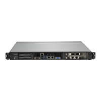
Displays main system features through front, control panel, and rear views.
Shows the locations of the main system components within the chassis.
Illustrates the motherboard layout with connectors, jumpers, and LEDs.
Visual representation of the motherboard's internal component connections.
Introduces rack mounting advice, unpacking, and setup preparation.
Provides instructions for identifying, assembling, and installing rack rails.
Steps for mounting the server chassis into the installed rack rails.
Specific instructions for installing the server chassis into a Telco rack.
Procedure for safely disconnecting power before performing maintenance.
Instructions for removing the chassis top cover to access internal parts.
Guide for installing the CPU, carrier assembly, and heatsink module (PHM).
Details memory support, population sequences, and mixing guidelines.
Procedure for replacing the system's non-volatile memory lithium battery.
Instructions for installing, removing, and managing storage drives and carriers.
Information on chassis fans, fan replacement, and air shroud installation.
Details on power supply LEDs and the procedure for changing modules.
Information on system's PCIe expansion slots and available riser cards.
Step-by-step guide for installing expansion cards into the chassis.
Pin definitions for ATX 24-pin and 8-pin CPU power connectors.
Describes chassis intrusion, BMC, fan headers, M.2 slots, and I/O ports.
Details on power button, reset button, LEDs, and NMI button connections.
Explanation of jumpers for BIOS recovery, ME recovery, and VGA settings.
Description of the onboard power LED and status code LED.
Guide for installing Windows OS, including driver loading.
Instructions for downloading and installing system drivers and utilities.
Overview of SuperDoctor 5 for system monitoring and management.
Information about the BMC for remote access and management.
Information on the system's hot-swap SATA storage drive bays.
Details on the Trusted Platform Module (TPM) for security.
Points to Supermicro website for support, manuals, FAQs, and direct links.
Instructions for accessing and using the BMC interface for monitoring.
General techniques and specific steps for diagnosing system issues.
Information on BIOS POST codes for error diagnosis during startup.
How to download crash dumps from the BMC dashboard for error analysis.
Procedures for recovering the UEFI BIOS image using various methods.
Steps for clearing the CMOS settings and passwords.
Methods for resetting the BMC to default configurations.
Guidance on where to purchase replacement parts from authorized distributors.
Steps for contacting technical support and returning merchandise.
Instructions on how to provide feedback regarding the user manual.
Detailed contact addresses, phone numbers, and emails for Supermicro.
Introduction to industry standard warnings for user safety.
Explanation of the universal warning symbol indicating potential danger.
Instruction to read installation procedures before connecting to power.
Warning regarding the building's short-circuit protection rating.
Warning to disconnect all power sources before accessing chassis interior.
Warning that only trained and qualified personnel should install equipment.
Warning about installing the unit in restricted access areas only.
Warning about the danger of explosion if the battery is replaced incorrectly.
Warning to disconnect all power connections for safety.
Warning about hazardous voltage or energy present on the backplane.
Warning to comply with local and national electrical codes during installation.
Warning regarding the ultimate disposal of the product according to laws.
Warning about hazardous moving parts in fan assemblies.
Warning to use only provided or designated power cables and adapters.
Details on the supported 4th Gen Intel Xeon Scalable processors.
Information about the Intel PCH C741 chipset.
Details on BIOS features including ACPI, PCI firmware, and RTC wakeup.
Specifications for supported DDR5 RDIMM memory up to 4TB.
Details on hot-swap SATA drive bays and M.2 NVMe support.
Information on PCIe 5.0 x16 slots and AIOM capabilities.
Details on rear and front I/O ports like LAN, USB, VGA, and COM.
Technical details of the X13SEDW-F motherboard.
Specifications for the 1U rackmount chassis CSE-LB16TS-R860AW3.
Details on the six 40x40x56mm counter-rotating PWM fans.
Specifications for the PWS-860P-1R2, 860W dual redundant power supplies.
Specifications for operating temperature and humidity.
List of regulatory compliance standards met by the system.
List of certified safety models associated with the system.
List of applicable directives and standards for EMC, safety, and environment.
Specific warning regarding perchlorate materials in lithium coin cells.
| Brand | Supermicro |
|---|---|
| Model | SuperServer SYS-111C-NR |
| Category | Server |
| Language | English |
