Chapter 6: Advanced Chassis Setup
6-17
6-10 Drive Bay Installation/Removal
Accessing the Drive Bays
SATA Drives: You do not need to access the inside of the chassis or remove power
to replace or swap SAS/SATA drives. Proceed to the next step for instructions. You
must use standard 1" high, SATA drives in the system.
Note: Refer to the following FTP site for setup guidelines: <ftp://ftp.supermicro.com/
driver/SAS/LSI/LSI_SAS_EmbMRAID_SWUG.pdf> and Supermicro's web site for
additional inmformation < http://www.supermicro.com/support/manuals/>.
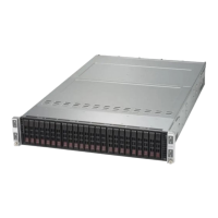
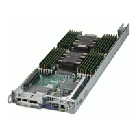
The SC217HQ+ chassis contains four individual motherboards in separate node
drawers. Each serverboard node controls a set of six hard drives. Note that if a
serverboard node drawer is pulled out of the chassis, the hard drives associated
with that node will power down as well.
Serverboard Drawer Locations in the Chassis
Serverboard B
Controls HDDs B1, B2, B3, B4, B5 and B6
Serverboard D
Controls HDDs D1, D2, D3, D4, D5 and D6
Serverboard A
Controls HDDs A1, A2, A3, A4, A5 and A6
Serverboard C
Controls HDDs C1, C2, C3, C4, C5 and C6
Figure 6-16. Hard Drives and the Corresponding Serverboards
SB: A
SB: B
SB: C
SB: D
1
A
1
B
1
C
1
D
 Loading...