10
SuperServer 4029GP-TRT/TRT2/TRT3 User's Manual
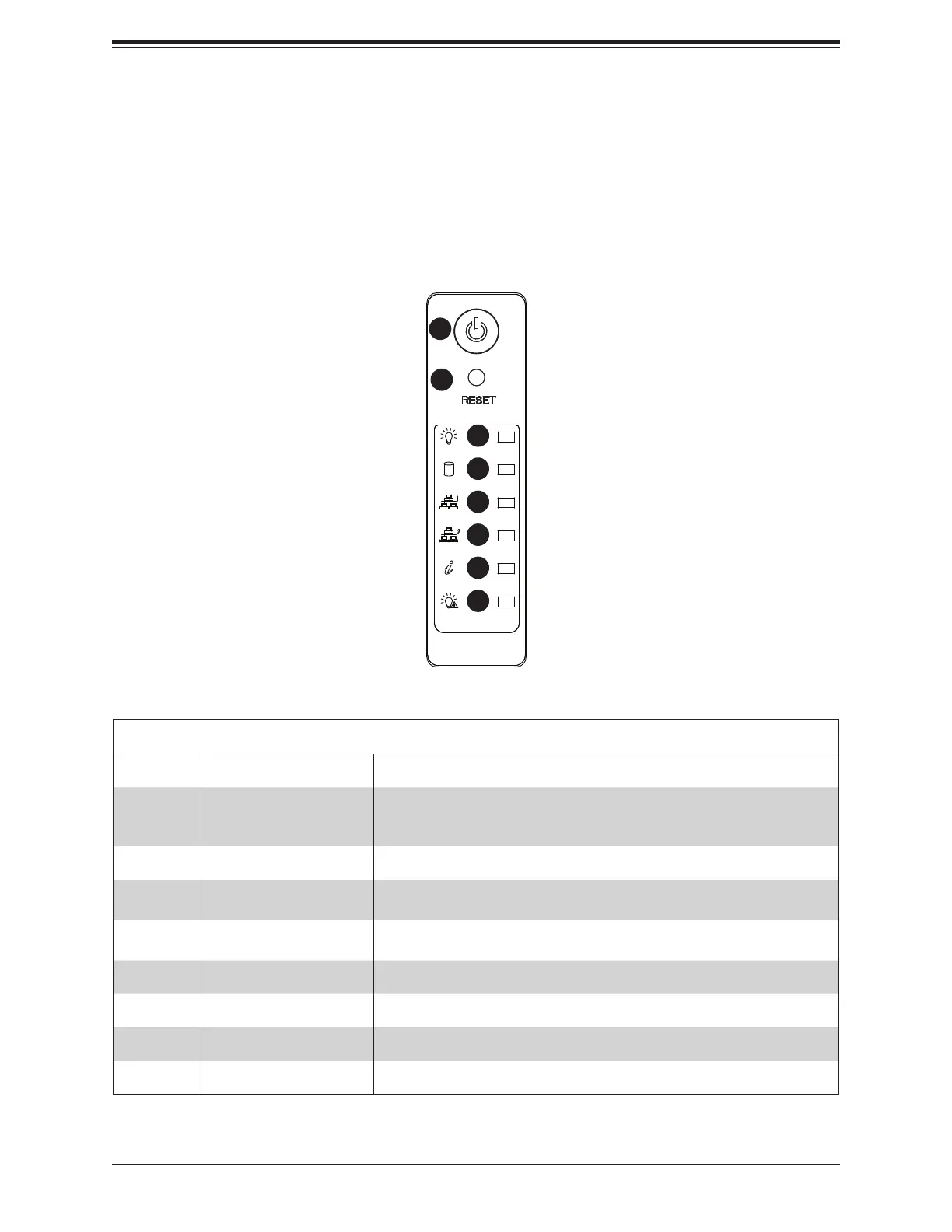
Control Panel Features
Item Feature Description
1 Power Button
The main power switch applies or removes primary power from the power
supply to the server but maintains standby power. To perform most maintenance
tasks, unplug the system to remove all power.
2 Reset Button The reset button is used to reboot the system.
3 Power LED
Indicates power is being supplied to the system power supply units. This LED is
illuminated when the system is operating normally.
4 HDD LED
Indicates IDE channel activity. SAS2/SATA drive and/or DVD-ROM drive activity
5 NIC1 LED
6 NIC2 LED
7 Universal Information LED See the following table for the status shown by this LED.
8 Power Fail LED Indicates a power supply module has failed.
Figure 1-1. Control Panel View
1.4 Server Chassis Features
Control Panel
button. In addition there are six LEDs. The locations of these buttons and LEDs on the control
panel are described below. See Chapter 4 for details on the control panel connections.
1
7
6
5
4
3
2
8
 Loading...