32
SuperServer E300-8D User's Manual
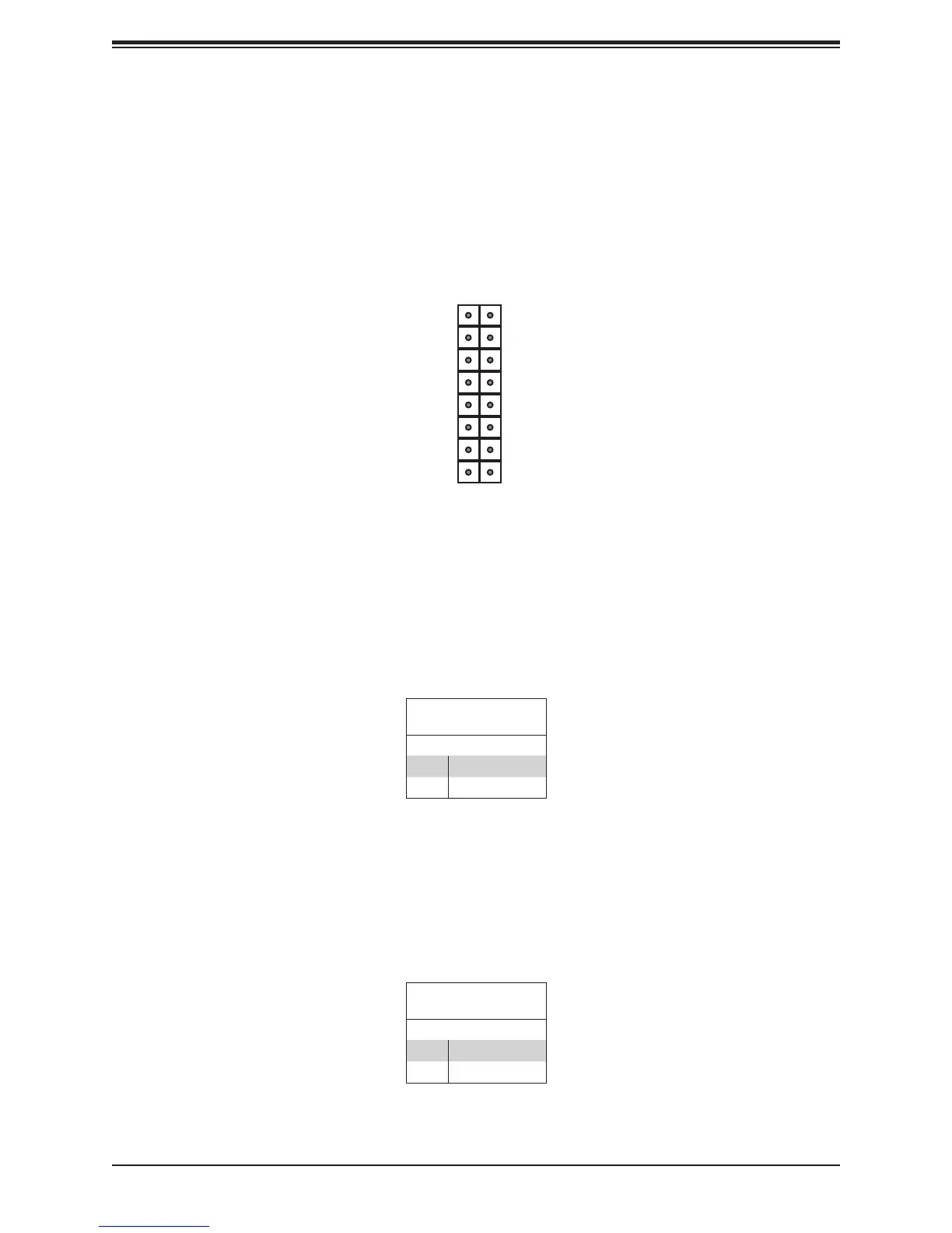
Figure 4-1. JF1: Control Panel Pins
Control Panel
All JF1 wires have been bundled into a single cable to simplify this connection. Make sure
the red wire plugs into pin 1 as marked on the motherboard. The other end connects to the
control panel PCB board.
3.3V
3.3V Standby
3.3V Standby
3.3V Standby
UID LED
3.3V
Reset Button (Data signal)
Power Button (Data signal)
Power On LED (Control signal)
HDD LED (Activity signal)
NIC1 LED (Ground)
NIC2 LED (Ground)
OH/Fan Fail LED (Ground)
Power Fail LED (Ground)
(Ground)
(Ground)
2 1
16 15
Power Button
Pin Denitions (JF1)
Pin# Denition
1 Signal
2 Ground
Power Button
The Power Button connection is located on pins 1 and 2 of JF1. Momentarily contacting both
button with a setting in the BIOS. To turn off the power when the system is in suspend mode,
press the button for 4 seconds or longer.
Reset Button
Pin Denitions (JF1)
Pin# Denition
3 Reset
4 Ground
Reset Button
The Reset Button connection is located on pins 3 and 4 of JF1. Attach it to a hardware reset
switch on the computer case.