29
Chapter 3 Motherboard Connections
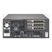
Figure 4-1. JF1: Control Panel Pins
Control Panel
All JF1 wires have been bundled into a single cable to simplify this connection. Make sure
the red wire plugs into pin 1 as marked on the motherboard. The other end connects to the
control panel PCB board.
Power Button
Pin Denitions (JF1)
Pin# Denition
1 Signal
2 Ground
Power Button
The Power Button connection is located on pins 1 and 2 of JF1. Momentarily contacting both
button with a setting in the BIOS. To turn off the power when the system is in suspend mode,
press the button for 4 seconds or longer.
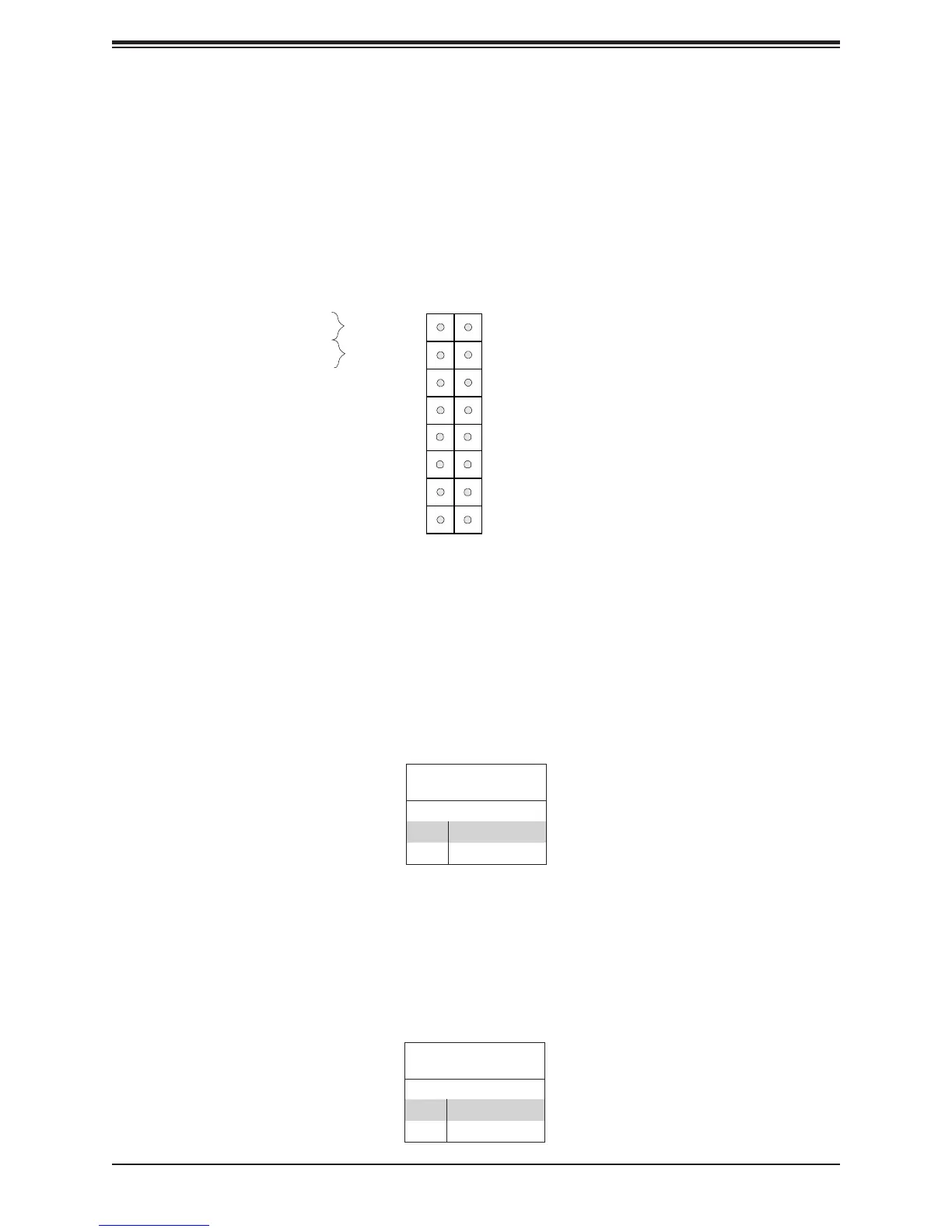
Reset Button
Pin Denitions (JF1)
Pin# Denition
3 Reset
4 Ground
Reset Button
The Reset Button connection is located on pins 3 and 4 of JF1. Attach it to a hardware reset
switch on the computer case.
Power Button
OH/Fan Fail/PWR Fail LED
NIC1 Activity LED
Reset Button
HDD LED
PWR LED
Reset
PWR
3.3V Stby
3.3V Stby
Ground
15
3.3V Stby
16
1 2
Ground
NIC2 Activity LED
Power Fail LED
UID
3.3V
3.3V