75
Chapter 4: Motherboard Connections
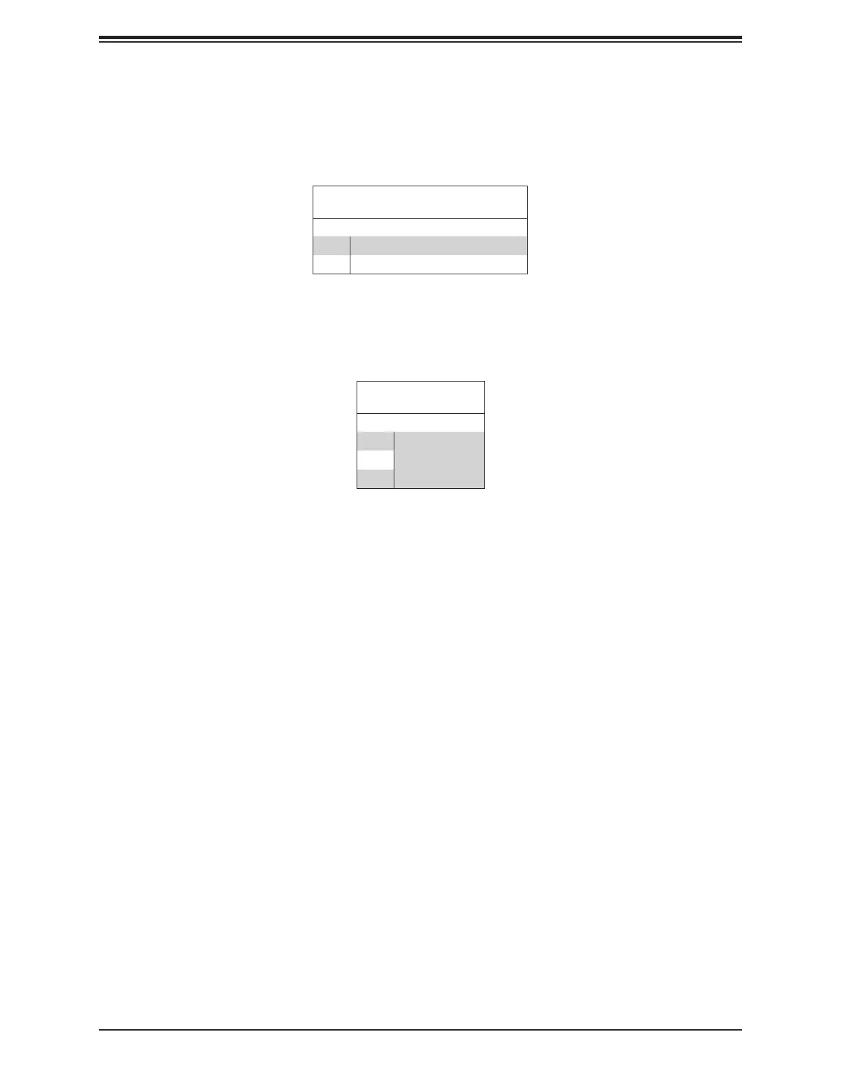
Power Fail LED Indicators
Power Failure LED Indicators are located on Pin 15 and Pin 19 of JF1. Refer to the table
FP Power LED
Pin Denitions (JF1)
Pin# Denition
15 PWR Failure LED-Positive
19 PWR Failure LED-Negative
FP USB Power
Pin 16 ~ Pin 18 are used to provide power to front USB devices. Refer to the table below
FP USB PWR
Pin Denitions
Pin# Denition
16
+5V USB PWR17
18
Front Control Panel Header 2
In addition to Front Control Panel header 1 (JF1), Front Control Panel header 2 (JFP2), also
located on the front side of the chassis, provides additional functions, including USB and
VGA support to the system.