74
Chapter 4: Motherboard Connections
LAN1/LAN2 (NIC1/NIC2)
The NIC (Network Interface Controller) LED connection for LAN Port 1 is located on Pin 6 of
JF1, and the connection for LAN Port 2 is on Pin 5. Refer to the tables below.
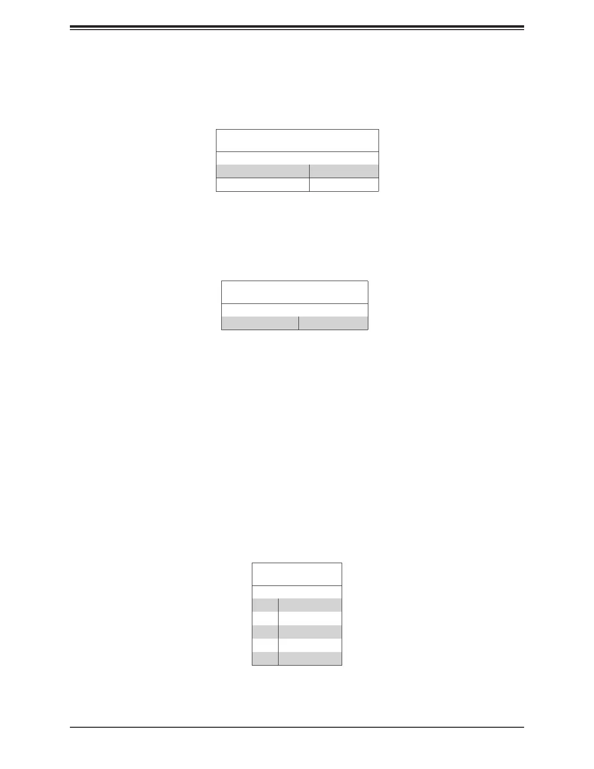
LAN1/LAN2 LED
LED States
Color State
NIC 2: Blinking green LAN 2: Active
NIC 1: Blinking green LAN 1: Active
HDD Activity LED
The HDD activity LED connection is located on Pin 7 of JF1. When this LED is blinking green,
it indicates HDD activity. Refer to the table below.
HDD LED
LED State
Color State
Blinking Green HDD Active
Standby Power LED
The LED indicator for standby power is located on Pin 8 of JF1. If this LED is on, standby
power is on.
RoT (Root of Trust) Power LED
The Power LED for RoT (Root of Trust) connection is located on Pin 9 of JF1. If this LED is
on, power for the RoT chip is on.
Standby Power
A Standby Power (I
2
C) connection is located on Pin 10 ~ Pin 14 of JF1 to provide power to
3.3V Standby PWR
Pin Denitions
Pin# Denition
10 P3V3 Standby
11 Ground
12 I²C Data
13 I²C Clock
14 Ground