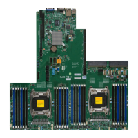
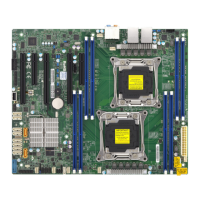
2-18
X10DRS-2U/3U/4U Motherboard User’s Manual
IPMI CODE
SAS CODE
MAC CODE
MAC CODE
X10DRS
REV:1.03
BAR CODE
BIOS
LICENSE
2-7 Control Panel Connectors and I/O Ports
The I/O ports are color-coded in conformance with industry standards. See the
picture below for the colors and locations of the various I/O ports. For proper
rear I/O support, an SMCI-proprietary backplane (BPN-SAS3-937, or BPN-SAS3-
927-N4) is required. See note 1 below.
Back Panel Connectors and I/O Ports (See Note 1 Below.)
Back Panel I/O Port Locations and Denitions
1. LAN 1 (shared w/IPMI LAN)
2. LAN 2
3. JKVM1: Keyboard/Video/Mouse/USB (2.0) 0/1
Port (SMCI cable: CBL-0218L required. See
Note 2 below.)
4. LEDL: System/Power LED (Green: Blinking:
System & power normal)
5. LEDH: BMC Heartbeat LED (Green: Blinking:
BMC normal)
6. External SAS supported by AOM-S3008-L8-SB
Note 1: An SMCI-proprietary backplane (BPN-SAS3-937, or BPN-SAS3-
927-N4) is required for your I/O back panel. Please install the backplane
indicated above on the rear of your chassis to ensure proper I/O backplane
setup.
Note 2: Please connect the SMCI-proprietary cable (CBL-0218L) to the
connector JKVM1 to provide video display/COM port/USB 2.0 support
for your system. Please refer to our website at www.supermicro.com for
more cable info.

 Loading...


