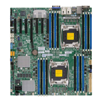
2-30
X10DRS-2U/3U/4U Motherboard User’s Manual
IPMI CODE
SAS CODE
MAC CODE
MAC CODE
M1
M2
M3
M7
M8
M9
M10
JPX1
JPL2
JPL1
JPME2
JPG1
JWD1
HDD_LED2
HDD_LED1
JTPM1
JSD2
FAN7
FAN8
FAN3
FAN6
FAN5
FAN2
FAN1
FAN4
JIPMB1
JBAT1
JBT1
JSLOT1
JKVM1
PM2
PM1
S-SATA0
GUI
LEDS_OV1
X10DRS
REV:1.03
BAR CODE
BIOS
LICENSE
LAN3
JSACT1
BMC
LEDH
LEDL
SAS
CPU1 PORT2
CPU2 PORT3
SLOT1 PCI-E 3.0 X24
FLASH
BMC
BIOS
USB3(3.0)
PCH
P2-DIMMG1
P2-DIMMH1
P2-DIMME1
P2-DIMMF1
P1-DIMMD1
P1-DIMMC1
P1-DIMMB1
P1-DIMMA1
SAS MEZZANINE Header
CPU2
JLAN1
JSD1
JPB1
LAN
CTRL
PLX
SAS
Expander
(Synch)
(PCI-E
Switch)
JDBS2
JSUART1
JSSDB1
JLAN2
JPWR1
JP1
JVRM1
JVRM2
1
1
1
1
CPU1
Battery
B
(PCH) HDD LED
The (PCH) HDD LED is located at HDD
LED1 on the motherboard. When this LED
is blinking, HDD supported by the Intel
PCH is active. See the table at right for
more information.
A
A. (PCH) HDD LED
B. SAS HDD LED
(PCH) HDD Activity LED
LED Settings
Color/State Denition
Green: Blinking PCH HDD:
Active
SAS HDD Activity LED
LED Settings
Color/State Denition
Green: Blinking SAS HDD:
Active
SAS HDD LED
The LED indicator for the SAS HDD is lo-
cated at HDD LED2 on the motherboard.
When this LED is blinking, the SAS HDD
supported by the LSI SAS controller is
active. See the table at right for more
information.

 Loading...


