Chapter 2: Installation
2-21
Front Panel Support & Power Connectors
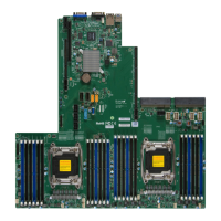
1. M1 2. M2
3. M3 4. Guide Pin
5. PM1 (Power Connector 1) 6. M4
7. M5 8. M6
9. M7 10. PM2 (Power Connector 2)
11. 4-pin PWR (on the motherboard)
Note: An SMCI-proprietary backplane is required for your front-panel sup-
port. Please install the required component on the front of your chassis
to ensure proper front-panel setup. Please refer to our website at www.
supermicro.com for more product info.
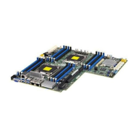
Front Panel Support and Power Connectors
An SMCI-proprietary front panel is used to provide front I/O support and power
connections for your system. Refer to the layout below for locations of the I/O front
panel and the 4-pin power connector. For more information on the I/O front panel or
back panel used in your system, please refer to our website at www.supermicro.com.
Front Panel Support and Power Connectors
11
10
IPMI CODE
SAS CODE
MAC CODE
MAC CODE
X10DRS
REV:1.03
BAR CODE
BIOS
LICENSE

 Loading...


