Chapter 2: Installation
2-23
IPMI CODE
SAS CODE
MAC CODE
MAC CODE
M1
M2
M3
M7
M8
M9
M10
JPX1
JPL2
JPL1
JPME2
JPG1
JWD1
HDD_LED2
HDD_LED1
JTPM1
JSD2
FAN7
FAN8
FAN3
FAN6
FAN5
FAN2
FAN1
FAN4
JIPMB1
JBAT1
JBT1
JSLOT1
JKVM1
PM2
PM1
S-SATA1
S-SATA0
GUI
LEDS_OV1
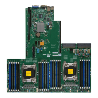
X10DRS
REV:1.03
BAR CODE
BIOS
LICENSE
LAN3
JSACT1
BMC
LEDH
LEDL
SAS
CPU1 PORT2
CPU2 PORT3
SLOT1 PCI-E 3.0 X24
FLASH
BMC
BIOS
USB3(3.0)
PCH
P2-DIMMG1
P2-DIMMH1
P2-DIMME1
P2-DIMMF1
P1-DIMMD1
P1-DIMMC1
P1-DIMMB1
P1-DIMMA1
SAS MEZZANINE Header
CPU2
JLAN1
JSD1
JPB1
LAN
CTRL
PLX
SAS
Expander
(Synch)
(PCI-E
Switch)
JDBS2
JSUART1
JSSDB1
JLAN2
JPWR1
JP1
JVRM1
JVRM2
1
1
1
1
CPU1
Battery
B
A
A. SATA DOM PWR (JSD1)
B. SATA DOM PWR (JSD2)
C. JIPMB1
DOM Power Connectors
Two power connectors for SATA DOM
(Disk-on-Module) devices are located
at JSD1/JSD2. Connect appropriate
cables here to provide power support
for your serial-link DOM devices.
DOM PWR
Pin Denitions
Pin# Denition
1 +5V
2 Ground
3 Ground
IPMB
A System Management Bus header
for IPMI 2.0 is located at JIPMB1.
Connect an appropriate cable here to
use the IPMB I
2
C connection on your
system.
IPMB Header
Pin Denitions
Pin# Denition
1 Data
2 Ground
3 Clock
4 No Connection
C

 Loading...


