54
X11SSL-CF/-nF User Manual
JPWR2
JPWR1
BMC
Intel PCH
IPMI_LAN
USB 0/1
JPWR2
USB 6/7
(3.0)
LAN 1
LAN 2
VGA
JTPM1
JPL1
JPL2
JD1
LED BMC
JIPMB1
JOH1
LE1
JUIDB1
USB 8 (3.0)
LED S1
LED PWR
FAN3
FANA
USB 4/5
USB 9/10 (3.0)
JSD1
I-SGPIO2
I-SGPIO1
JSD2
JL1
JBT1
JSTBY1
JPS1
X11SSL-CF_(-nF)
REV:1.01
Designed in the USA
SP1
JPG1
JBR1
JPME2
JPB1
JI2C2
SP1
JI2C1
JF1
JPI2C1
FAN1
FAN2
USB 2/3
PCH SLOT4 PCI-E 3.0 x1
PCH SLOT5 PCI-E 3.0 x4(in x8)
CPU SLOT6 PCI-E 3.0 x8(in x16)
I-SATA5
I-SATA1
I-SATA4
I-SATA3 I-SATA2
I-SATA0
JWD1
DIMMB2
DIMMB1
DIMMA2
DIMMA1
JSAS1
JNVME1
LSI 3008
CPU
BT1
MEGERAC
LICENSE
1
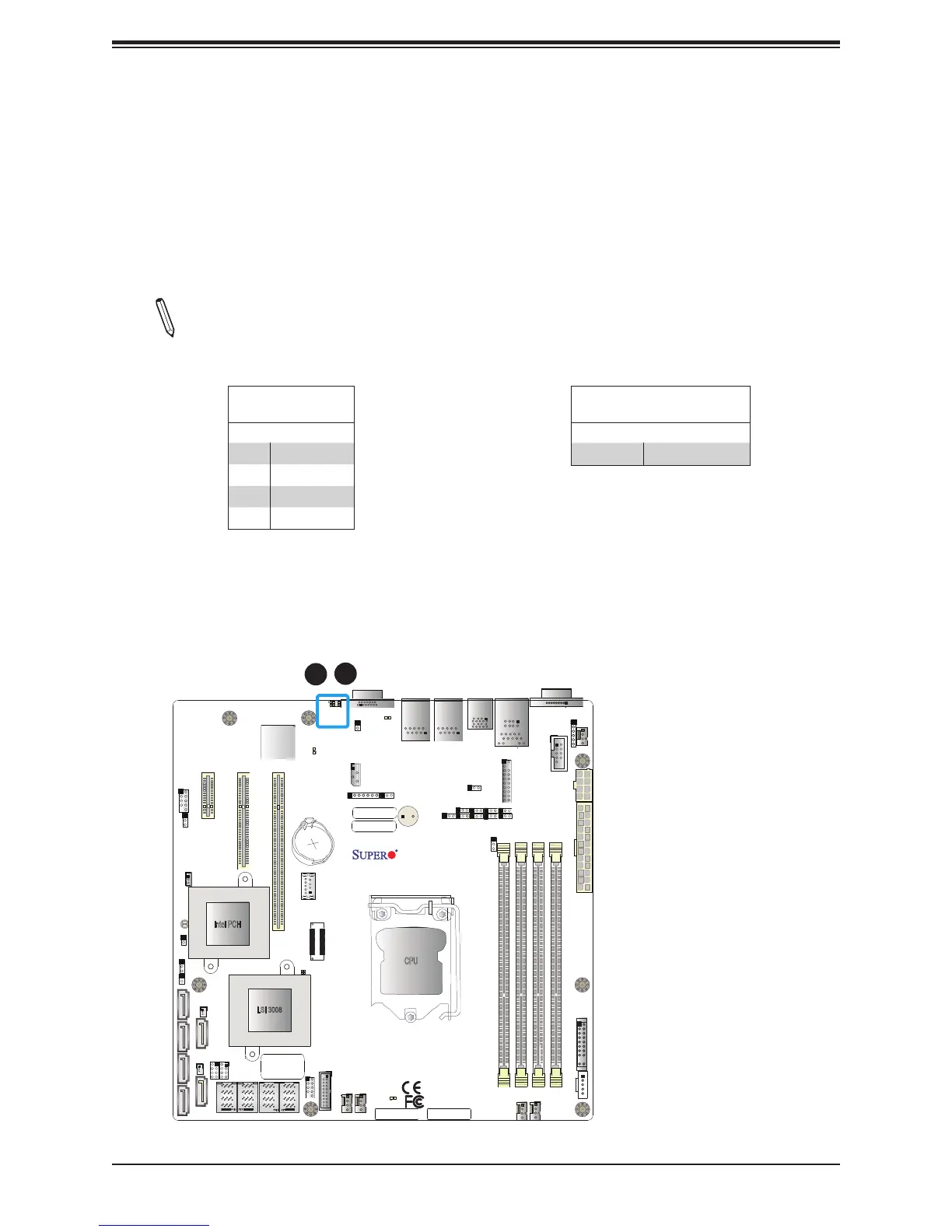
1. UID Switch
2. UID LED
2
Unit Identier Switch/UID LED Indicator
A rear Unit Identier (UID) switch and a rear UID LED (LE1) are located next to the VGA port
on the motherboard. The front UID switch and the front UID LED are both located on the
Front Panel Control (JF1) (with the front UID switch on pin 13, and the front LED on pin 7
of JF1). When you press the front or the rear UID switch, both front and rear UID LEDs will
be turned on. Press the UID switch again to turn off the LED indicators. The UID Indicators
provide easy identication of a system unit that may be in need of service.
Note: UID can also be triggered via IPMI on the motherboard. For more information
on IPMI, please refer to the IPMI User's Guide posted on our website at http://www.
supermicro.com.
UID Switch
Pin Denitions
Pin# Denition
1 Ground
2 Ground
3 Button In
4 Ground
UID LED
Pin Denitions
Color Status
Blue: On Unit Identied

 Loading...


