58
X11SSL-CF/-nF User Manual
JPWR2
JPWR1
BMC
Intel PCH
IPMI_LAN
USB 0/1
JPWR2
USB 6/7
(3.0)
LAN 1
LAN 2
VGA
JTPM1
JPL1
JPL2
JD1
LED BMC
JIPMB1
JOH1
LE1
JUIDB1
USB 8 (3.0)
LED S1
LED PWR
FAN3
FANA
USB 4/5
USB 9/10 (3.0)
JSD1
I-SGPIO2
I-SGPIO1
JSD2
JL1
JBT1
JSTBY1
JPS1
X11SSL-CF_(-nF)
REV:1.01
Designed in the USA
SP1
JPG1
JBR1
JPME2
JPB1
JI2C2
SP1
JI2C1
JF1
JPI2C1
FAN1
FAN2
USB 2/3
PCH SLOT4 PCI-E 3.0 x1
PCH SLOT5 PCI-E 3.0 x4(in x8)
CPU SLOT6 PCI-E 3.0 x8(in x16)
I-SATA5
I-SATA1
I-SATA4
I-SATA3 I-SATA2
I-SATA0
JWD1
DIMMB2
DIMMB1
DIMMA2
DIMMA1
JSAS1
JNVME1
LSI 3008
CPU
BT1
MEGERAC
LICENSE
1
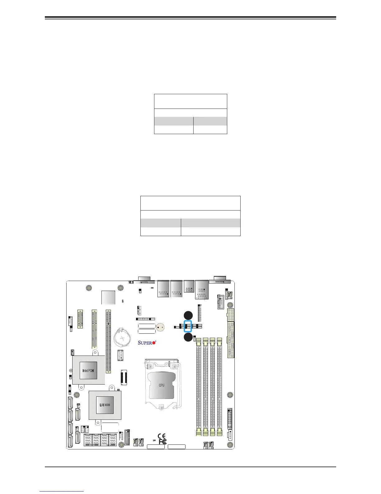
1. VGA Enable
2. BIOS Recovery Enable
2
VGA Enable/Disable
Jumper JPG1 allows the user to enable the onboard VGA connector. The default setting is
pins 1-2 to enable the connection. Refer to the table below for jumper settings.The default
setting is Enabled.
VGA Enable/Disable
Jumper Settings
Jumper Setting Denition
Pins 1-2 Enabled
Pins 2-3 Disabled
BIOS Recovery
Use jumper JBR1 to recover the BIOS settings on the motherboard. Refer to the table below
for jumper settings. The default setting is Normal.
BIOS Recovery
Jumper Settings
Jumper Setting Denition
Pins 1-2 Normal
Pins 2-3 BIOS Recovery

 Loading...


