59
Chapter 2: Installation
JPWR2
JPWR1
BMC
Intel PCH
IPMI_LAN
USB 0/1
JPWR2
USB 6/7
(3.0)
LAN 1
LAN 2
VGA
JTPM1
JPL1
JPL2
JD1
LED BMC
JIPMB1
JOH1
LE1
JUIDB1
USB 8 (3.0)
LED S1
LED PWR
FAN3
FANA
USB 4/5
USB 9/10 (3.0)
JSD1
I-SGPIO2
I-SGPIO1
JSD2
JL1
JBT1
JSTBY1
JPS1
X11SSL-CF_(-nF)
REV:1.01
Designed in the USA
SP1
JPG1
JBR1
JPME2
JPB1
JI2C2
SP1
JI2C1
JF1
JPI2C1
FAN1
FAN2
USB 2/3
PCH SLOT4 PCI-E 3.0 x1
PCH SLOT5 PCI-E 3.0 x4(in x8)
CPU SLOT6 PCI-E 3.0 x8(in x16)
I-SATA5
I-SATA1
I-SATA4
I-SATA3 I-SATA2
I-SATA0
JWD1
DIMMB2
DIMMB1
DIMMA2
DIMMA1
JSAS1
JNVME1
LSI 3008
CPU
BT1
MEGERAC
LICENSE
1
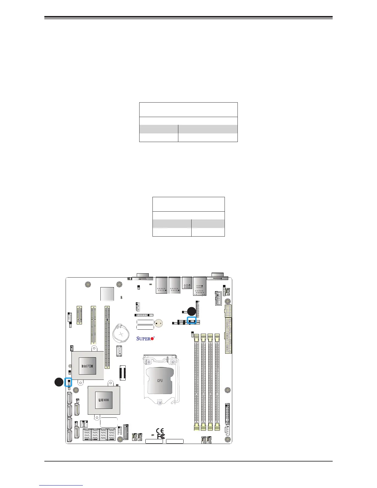
1. Manufacterer Mode
Select
2. SAS Status
2
Manufacturer Mode Select
Close pin 2 and pin 3 of jumper JPME2 to bypass SPI ash security and force the system to
operate in the manufacturer mode, which will allow the user to ash the system rmware from
a host server for system setting modications. Refer to the table below for jumper settings.
The default setting is Normal.
Manufacturer Mode
Jumper Settings
Jumper Setting Denition
Pins 1-2 Normal
Pins 2-3 Manufacturer Mode
SAS Status
Jumper Settings
Jumper Setting Denition
Pins 1-2 Enabled
Pins 2-3 Disabled
SAS Status (For -CF models only)
JPS1 allows the user to enable the SAS status indicator at LEDS1. The default setting is
Enabled.See the table below for jumper settings.

 Loading...


