2-20
X8DTU/X8DTU-F User's Manual
Power Button
1
NIC1 (Link) LED
Reset Button
2
HDD LED
Power LED
Reset
PWR
3.3V
3.3V SB
Ground
Ground
1920
3.3 V
Key
Ground
NMI
PWR Fail LED
NIC2 (Link) LED
OH/Fan Fail/PWR
Fail/Blue_UID LED
Red_LED_Cathode
(UID)/5V SB
NIC1 (Activity) LED
NIC2 (Activity) LED
Key
X8DTU/-F
A
B
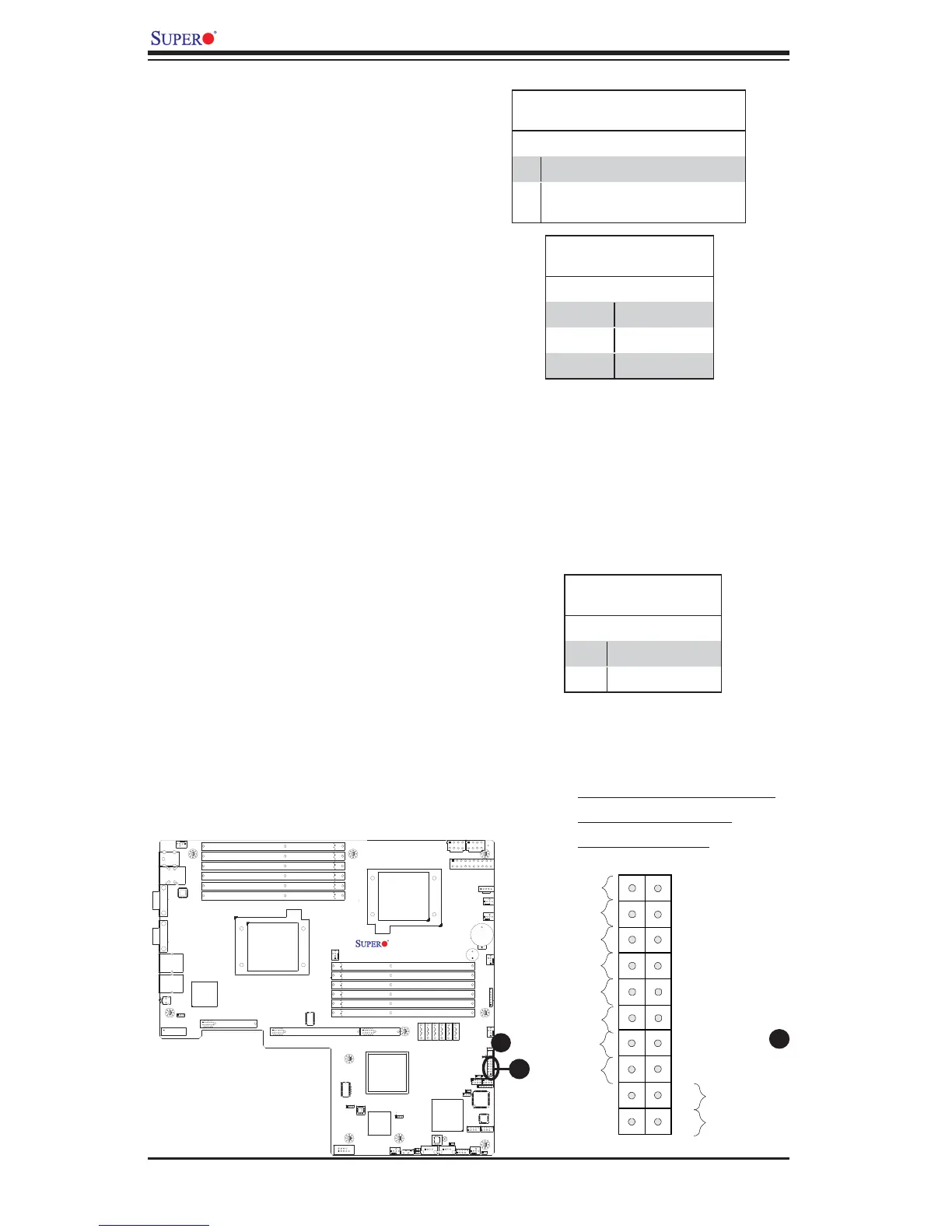
A. OH/Fan Fail/PWR Fail LED
B. Blue LED (UID LED)
C. PWR Supply Fail
Overheat (OH)/Fan Fail/PWR Fail/UID
LED
Connect an LED cable to pins 7 and 8 of
JF1 to use the Overheat/Fan Fail/Power
Fail and UID LED connections. The Red
LED on pin 7 provides warnings of an
overheat, fan failure or power failure.
The Blue LED on pin 8 works as the front
panel UID LED indicator. The Red LED
takes precedence over the Blue LED by
default. Refer to the table on the right for
pin defi nitions.
Power Fail LED
The Power Fail LED connection is lo-
cated on pins 5 and 6 of JF1. Refer to the
table on the right for pin defi nitions.
OH/Fan Fail/ PWR Fail/Blue_UID
LEDPin Defi nitions (JF1)
Pin# Defi nition
7 Red_LED-Cathode (UID)/5.5V.SB
8 OH/Fan Fail/PWR Fail/Blue_UID
LED
OH/Fan Fail/PWR Fail
LED Status (Red LED)
State Defi nition
Off Normal
On Overheat
Flashing Fan Fail
PWR Fail LED
Pin Defi nitions (JF1)
Pin# Defi nition
5 3.3V
6 PWR Fail LED
C
 Loading...