2-22
X8DTU/X8DTU-F User's Manual
Warning: To prevent damage to your power supply or motherboard, please
use a power supply that contains a 24-pin and two 8-pin power connec-
tors. Be sure to connect these power connectors to the 24-pin and the two
8-pin power connectors on your motherboard for adequate power supply
to your system. Failure to do so will void the manufacturer warranty on
your power supply and motherboard.
KB /MS
Fan8
(CPU2 Fan)
IPMI LAN
USB 0/1
COM1
PHY
VGA
LAN1
LAN2
LAN CTRL
BMC CTRL
BIOS
COM2
USB6
USB7
USB4/5
(ME Rec.)
JTAG Of CPLD
ME Mode
JPI2C
P2-DIMM3A
P2-DIMM3B
P2-DIMM2A
P2-DIMM2B
P2-DIMM1A
P2-DIMM1B
P1-DIMM1B
P1-DIMM1A
P1-DIMM2B
P1-DIMM2A
P1-DIMM3B
P1-DIMM3A
LE2
JUIDB
JPL1
J10
UIOP
SXB2: PCI-E 2.0 x 8
SXB1: PCI-E 2.0 x 16
SXB3: PCI-E 2.0 x 8 in x 4 Slot
J1
J2
J3
JPB
JPG1
Fan6
IPMB
JI2C1
JI2C2
JBT1
J13
J14
JP5
J12
Fan5
JL1
USB2/3 JLPC1
CPU1
CPU2
Intel I5520
North Bridge
Intel ICH10R
South Bridge
T-SGPIO2
J17
JPRST1
JWD
JF1
JOH1
JP3
LE1
Fan4
Fan3
SP1
Buzzer
JBAT1
Battery
Fan2
Fan1
JPW1
JPW3
JPW2
I-SATA5
I-SATA4
I-SATA3
I-SATA2
I-SATA1
I-SATA0
X8DTU/-F
Fan7(CPU1 Fan)
FP CTRL
CPLD
PWRLED/SPK
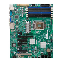
ATX Power Connector
There are a 20-pin main power
supply connector(JPW1) and two
8-pin CPU PWR connectors (JPW2/
JPW3) on the motherboard. These
power connectors meet the SSI EPS
12V specifi cation. For the 8-pin PWR
(JPW2/JPW3), please refer to the item
listed below.
Processor Power Connector
In addition to the Primary ATX power
connector, the 12V 8-pin CPU PWR
connectors at JPW2/JPW3 must also
be connected to your power supply.
See the table on the right for pin
defi nitions.
12V 8-pin Power Con-
nector
Pin Defi nitions
Pins Defi nition
1 through 4 Ground
5 through 8 +12V
A. 20-pin ATX PWR
B/C.8-pin Processor PWR
(Required)
B
C
2-6 Connecting Cables
20-pin Main Power Connector
Pin Defi nitions
Pin# Defi nition Pin # Defi nition
11 PS On 1 Ground
12 5VSB 2 Ground
13 Ground 3 Ground
14 Ground 4 Ground
15 Ground 5 Ground
16 NC2 6 NC1
17 12V 7 12V
18 12V 8 12V
19 12V 9 12V
20 12V 10 12V
(Required)
 Loading...