Chapter 2: Installation
2-29
KB /MS
Fan8
(CPU2 Fan)
IPMI LAN
USB 0/1
COM1
PHY
VGA
LAN1
LAN2
LAN CTRL
BMC CTRL
BIOS
COM2
USB6
USB7
USB4/5
(ME Rec.)
JTAG Of CPLD
ME Mode
JPI2C
P2-DIMM3A
P2-DIMM3B
P2-DIMM2A
P2-DIMM2B
P2-DIMM1A
P2-DIMM1B
P1-DIMM1B
P1-DIMM1A
P1-DIMM2B
P1-DIMM2A
P1-DIMM3B
P1-DIMM3A
LE2
JUIDB
JPL1
J10
UIOP
SXB2: PCI-E 2.0 x 8
SXB1: PCI-E 2.0 x 16
SXB3: PCI-E 2.0 x 8 in x 4 Slot
J1
J2
J3
JPB
JPG1
Fan6
IPMB
JI2C1
JI2C2
JBT1
J13
J14
JP5
J12
Fan5
JL1
USB2/3 JLPC1
CPU1
CPU2
Intel I5520
North Bridge
Intel ICH10R
South Bridge
T-SGPIO2
J17
JPRST1
JWD
JF1
JOH1
JP3
LE1
Fan4
Fan3
SP1
Buzzer
JBAT1
Battery
Fan2
Fan1
JPW1
JPW3
JPW2
I-SATA5
I-SATA4
I-SATA3
I-SATA2
I-SATA1
I-SATA0
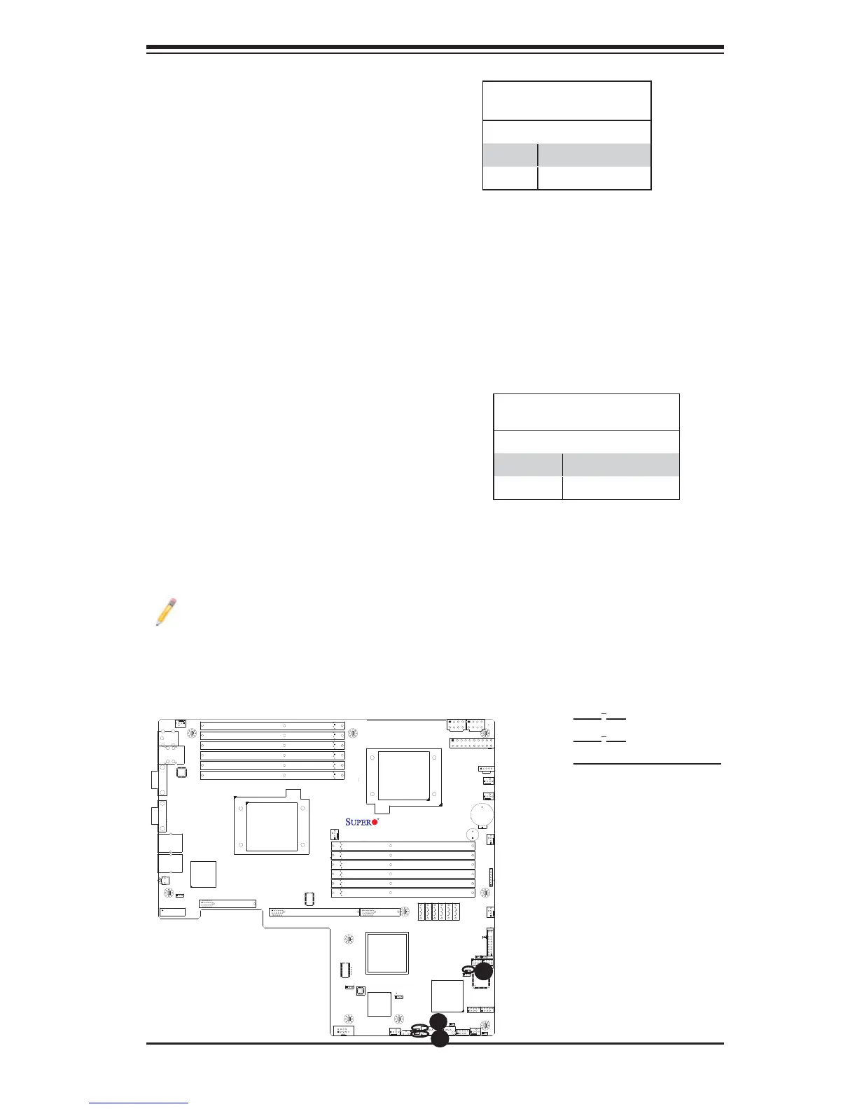
X8DTU/-F
Fan7(CPU1 Fan)
FP CTRL
CPLD
PWRLED/SPK
A
A. JI
2
C1
B. JI
2
C2
C. BMC & PHY Reset
B
I
2
C Bus to PCI-Exp. Slots
Jumpers JI
2
C1 and JI
2
C2 allow you to
connect the System Management Bus
(I
2
C) to PCI-Express slots. The default
setting is Open to disable the connec-
tion. See the table on the right for jumper
settings.
I
2
C to PCI-Exp
Jumper Settings
Jumper Setting Defi nition
1-2 Enabled
2-3 Disabled (Default)
C
BMC/PHY Reset (X8DTU-F)
Jumper JPRST1 allow the user to reset
the Winbond WPCM450 BMC (Base-
board Management Controller) chip and
the PHY chip. The default is set to Off
for normal operation. See the table on
the right for jumper settings.
BMC/PHY
Jumper Settings
Jumper Setting Defi nition
On Reset BMC & PHY
Off Normal (Default)
Note: For more information on IPMI confi guration instructions, please refer
to the Embedded Winbond BMC IPMI user guide posted on our website @
http://www.supermicro.com/support/manuals/.
 Loading...