Chapter 2: Installation
2-27
KB /MS
Fan8
(CPU2 Fan)
IPMI LAN
USB 0/1
COM1
PHY
VGA
LAN1
LAN2
LAN CTRL
BMC CTRL
BIOS
COM2
USB6
USB7
USB4/5
(ME Rec.)
JTAG Of CPLD
ME Mode
JPI2C
P2-DIMM3A
P2-DIMM3B
P2-DIMM2A
P2-DIMM2B
P2-DIMM1A
P2-DIMM1B
P1-DIMM1B
P1-DIMM1A
P1-DIMM2B
P1-DIMM2A
P1-DIMM3B
P1-DIMM3A
LE2
JUIDB
JPL1
J10
UIOP
SXB2: PCI-E 2.0 x 8
SXB1: PCI-E 2.0 x 16
SXB3: PCI-E 2.0 x 8 in x 4 Slot
J1
J2
J3
JPB
JPG1
Fan6
IPMB
JI2C1
JI2C2
JBT1
J13
J14
JP5
J12
Fan5
JL1
USB2/3 JLPC1
CPU1
CPU2
Intel I5520
North Bridge
Intel ICH10R
South Bridge
T-SGPIO2
J17
JPRST1
JWD
JF1
JOH1
JP3
LE1
Fan4
Fan3
SP1
Buzzer
JBAT1
Battery
Fan2
Fan1
JPW1
JPW3
JPW2
I-SATA5
I-SATA4
I-SATA3
I-SATA2
I-SATA1
I-SATA0
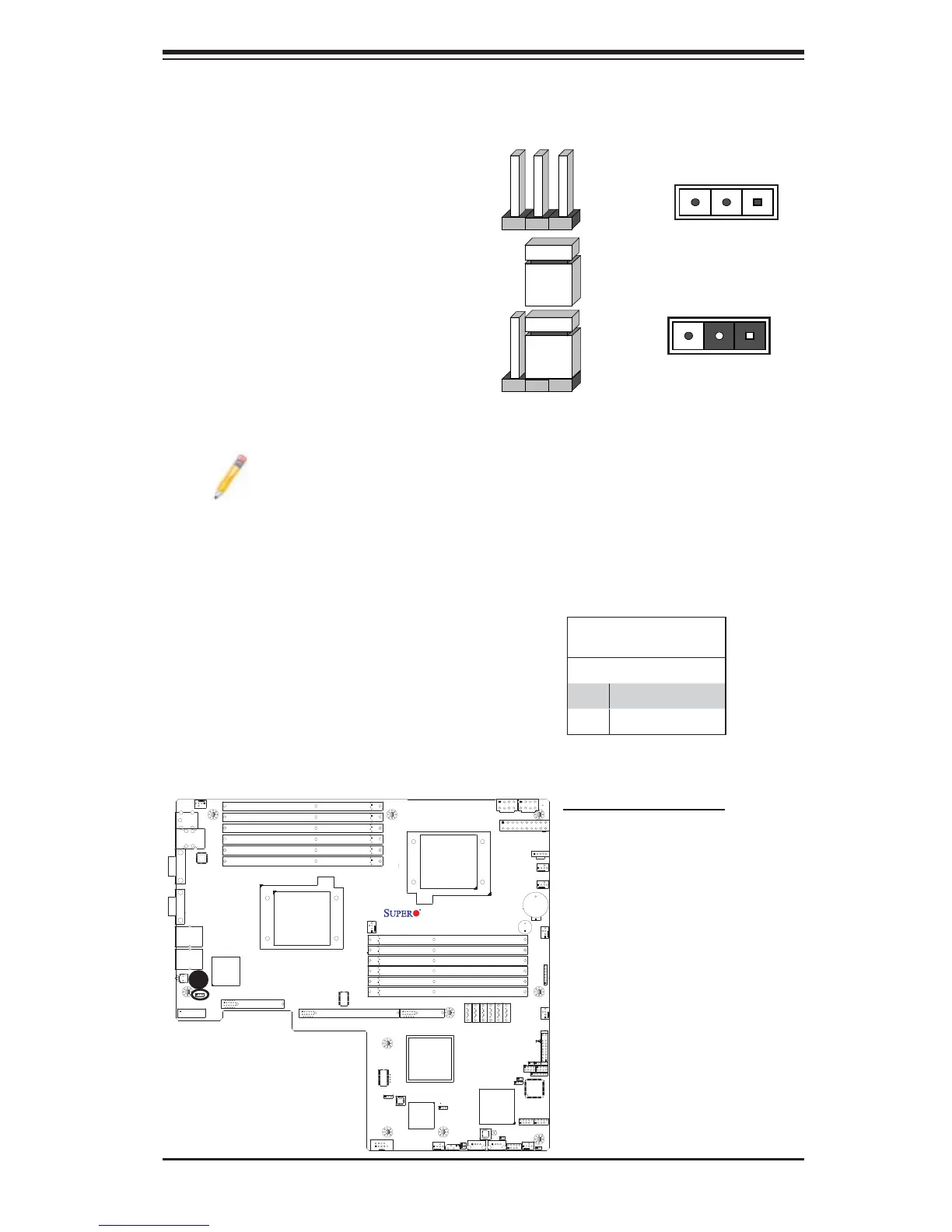
X8DTU/-F
Fan7(CPU1 Fan)
FP CTRL
CPLD
PWRLED/SPK
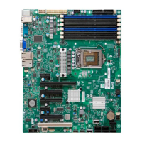
2-7 Jumper Settings
Explanation of Jumpers
To modify the operation of the mother-
board, jumpers can be used to choose
between optional settings. Jumpers cre-
ate shorts between two pins to change
the function of the connector. Pin 1
is identifi ed with a square solder pad
on the printed circuit board. See the
motherboard layout pages for jumper
locations.
Note: On two pin jumpers,
"Closed" means the jumper
is on and "Open" means the
jumper is off the pins.
Connector
Pins
Jumper
Cap
Setting
Pin 1-2 short
3 2 1
3 2 1
GLAN Enable/Disable
JPL1 enable or disable the GLAN
Port1/GLAN Port2 on the mother-
board. See the table on the right for
jumper settings. The default setting is
Enabled.
GLAN Enable
Jumper Settings
Pin# Defi nition
1-2 Enabled (default)
2-3 Disabled
A
A. LAN Ports 1/2 Enable