2-28
X8DTU/X8DTU-F User's Manual
KB /MS
Fan8
(CPU2 Fan)
IPMI LAN
USB 0/1
COM1
PHY
VGA
LAN1
LAN2
LAN CTRL
BMC CTRL
BIOS
COM2
USB6
USB7
USB4/5
(ME Rec.)
JTAG Of CPLD
ME Mode
JPI2C
P2-DIMM3A
P2-DIMM3B
P2-DIMM2A
P2-DIMM2B
P2-DIMM1A
P2-DIMM1B
P1-DIMM1B
P1-DIMM1A
P1-DIMM2B
P1-DIMM2A
P1-DIMM3B
P1-DIMM3A
LE2
JUIDB
JPL1
J10
UIOP
SXB2: PCI-E 2.0 x 8
SXB1: PCI-E 2.0 x 16
SXB3: PCI-E 2.0 x 8 in x 4 Slot
J1
J2
J3
JPB
JPG1
Fan6
IPMB
JI2C1
JI2C2
JBT1
J13
J14
JP5
J12
Fan5
JL1
USB2/3 JLPC1
CPU1
CPU2
Intel I5520
North Bridge
Intel ICH10R
South Bridge
T-SGPIO2
J17
JPRST1
JWD
JF1
JOH1
JP3
LE1
Fan4
Fan3
SP1
Buzzer
JBAT1
Battery
Fan2
Fan1
JPW1
JPW3
JPW2
I-SATA5
I-SATA4
I-SATA3
I-SATA2
I-SATA1
I-SATA0
X8DTU/-F
Fan7(CPU1 Fan)
FP CTRL
CPLD
PWRLED/SPK
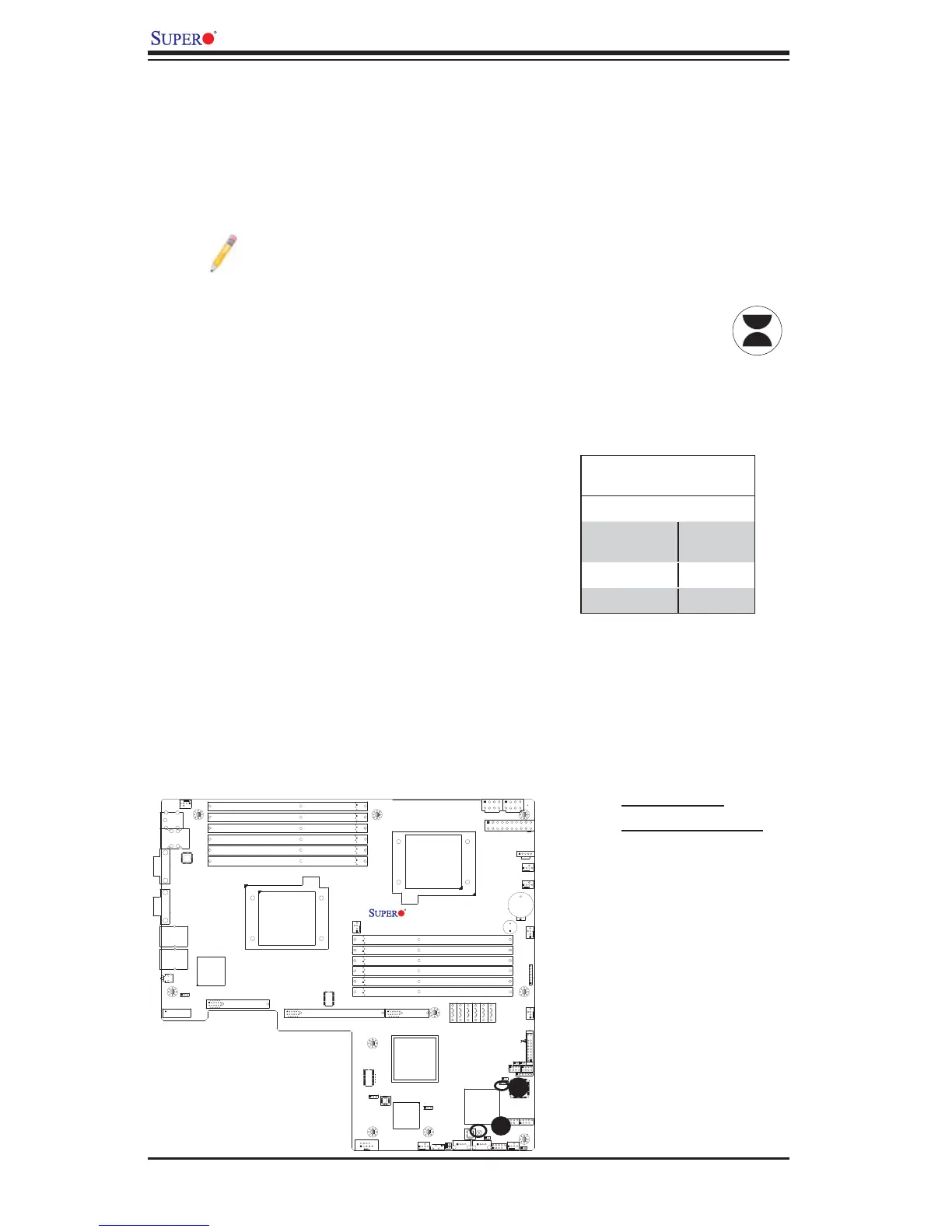
CMOS Clear
JBT1 is used to clear CMOS. Instead of pins, this "jumper" consists of contact pads
to prevent the accidental clearing of CMOS. To clear CMOS, use a metal object such
as a small screwdriver to touch both pads at the same time to short the connection.
Always remove the AC power cord from the system before clearing CMOS.
Note: For an ATX power supply, you must completely shut down the sys-
tem, remove the AC power cord and then short JBT1 to clear CMOS.
A
B
A. Clear CMOS
B. Watch Dog Enable
Watch Dog Enable/Disable
Watch Dog (JWD) is a system monitor that
can reboot the system when a software ap-
plication hangs. Close Pins 1-2 to reset the
system if an application hangs. Close Pins
2-3 to generate a non-maskable interrupt
signal for the application that hangs. See the
table on the right for jumper settings. Watch
Dog must also be enabled in the BIOS.
Watch Dog
Jumper Settings (JWD)
Jumper Setting Defi nition
Pins 1-2 Reset
(default)
Pins 2-3 NMI
Open Disabled