Chapter 2: Installation
2-9
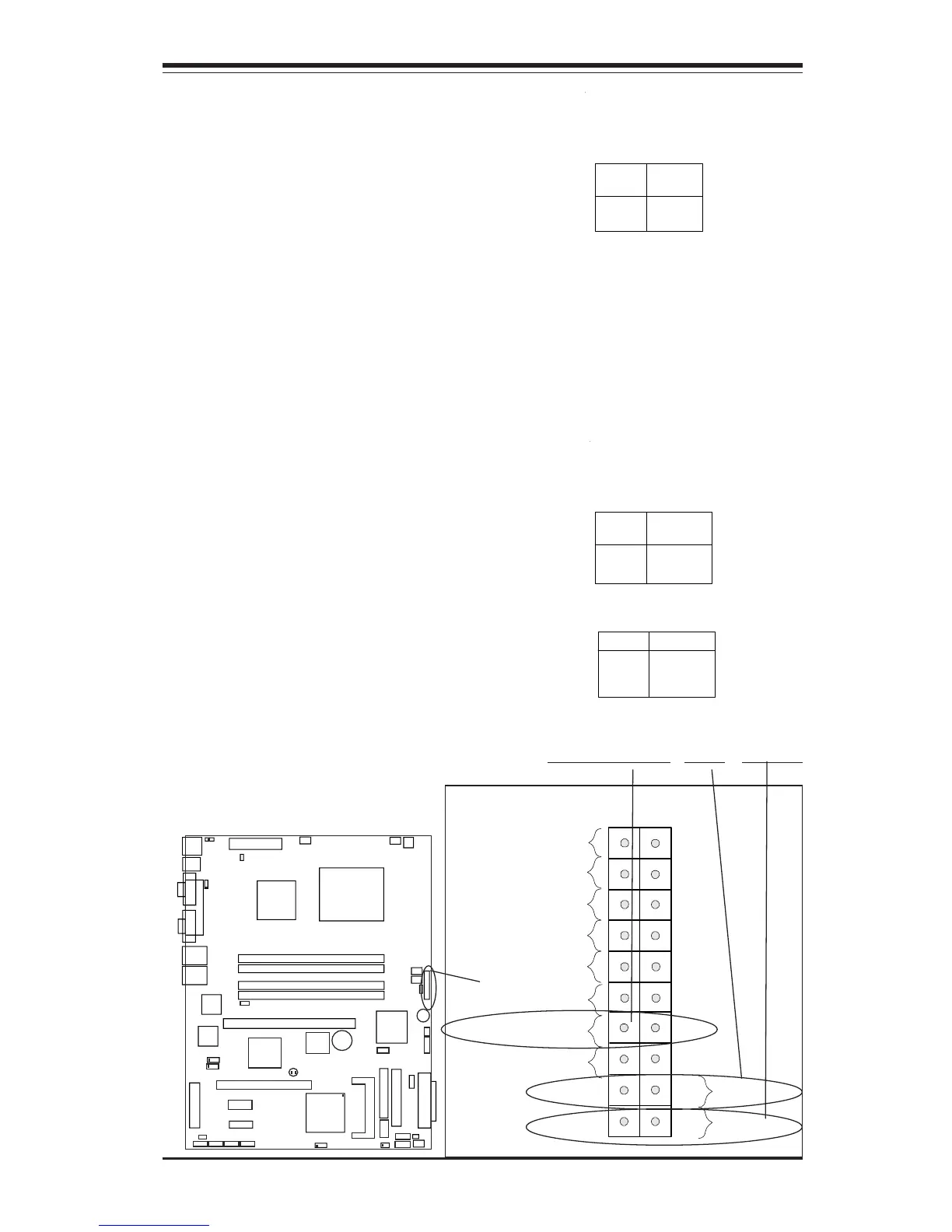
Pin
Number
3
4
Definition
Reset
Ground
Reset Pin
Definitions
(JF1)
Reset Connector
The reset connector is located on
pins 3 and 4 of JF1. This connec-
tor attaches to the reset switch on
the computer chassis. See the
table on the right for pin defini-
tions.
NIC1 LED
Power Butto
2
IDE/SATA LED
Power On LED
Reset
Signal
Vcc
Vcc
Vcc
Vcc
Ground
3V Standby
1920
Vcc
X
Ground
NMI
X
X
X
NIC2 LED
KB/MS
USB0/1
COM1
VGA
Parallel Port
JPUSB1
ATX-24 Pin PWR
JPF
JPWAKE1
4-Pin
PWR
CPU
CopperRiver
NorthBridge
GLAN1
GLAN2
DIMM 1A
DIMM 1B
DIMM 2A
DIMM 2B
GLAN
CTRL
GLAN
CTRL
JPL1
JPL2
PCI-X 133/100 MHz
PCI-Ex1
(L
G
A
7
7
5
)
SCSI CTRL
7902 W
S
C
S
I C
h
a
n
n
e
l A
SCSI Channel B
J
W
D
U
S
B
6
/7
B
IO
S
J
L
1
ID
E
F
lo
p
p
y
J
5
J
B
T
1
J
F
1
J
L
E
D
F
a
n
3
F
a
n
2
J
S
L
E
D
Fan1
Fan5
Fan4
IC
H
6
R
S
o
u
th
B
rid
g
e
PXH-V
PCI 33MHz
B
a
tte
ry
PCI-Ex1
S
A
T
A
3
S
A
T
A
2
S
A
T
A
1
S
A
T
A
0
J
W
O
R
J
P
A
1
IP
M
I
C
O
M
2
U
S
B
2
/3
B
u
z
z
e
r
W
O
L
JBT1
J
9
J
S
L
E
D
LE1
E7221
PWR-OnResetOH/Fan Fail LED
Overheat/FanFail LED
Connect an LED to the OH/Fan Fail
connection on pins 7 and 8 of JF1
to provide advanced warning of
chassis overheating or system fan
failure. Refer to the table on the
right for pin definitions.
Overheat (OH) LED
Pin Definitions
(JF1)
Pin
Number
7
8
Definition
Vcc
GND
OH/Fan Fail LED
(JF1)
State
Off
Stay On
Blink
Message
Normal
Overheat
Fan Fail