Chapter 2: Installation
2-13
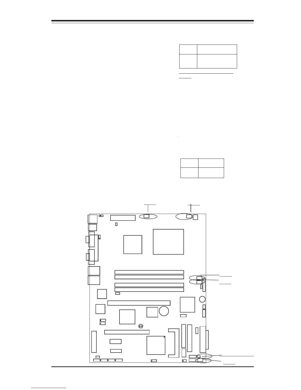
Chassis Intrusion
The Chassis Intrusion header is
located at JL1. See the board lay-
out in Chapter 1 for the location of
JL1 and the table on the right for
pin definitions.
Pin
Number
1
2
Definition
Intrusion Inpu
Ground
Chassis Intrusion
Pin Definitions (JL1)
Fan Headers
There are five fan headers (Fan 1
to Fan5) on the P8SC8/P8SCi.
See the table on the right for pin
definitions. These fan headers
support 3-pin fans. The fan speed
is controlled by Thermal Manage-
ment under the Hardware Monitor-
ing Section in the BIOS.