2-18
P8SC8/P8SCi User's Manual
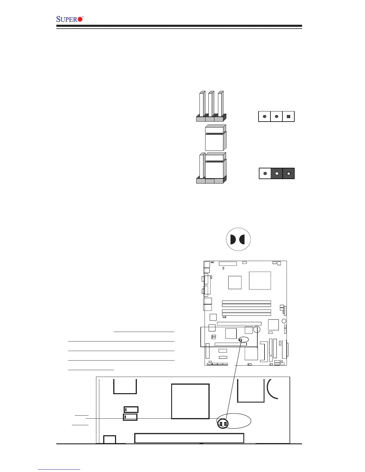
CMOS Clear
JBT1 is not actually a jumper but
consists of two contact pads. To
clear the contents of CMOS, short
these pads together by touching
them both with a metal conductor
such as the head of a small
screwdriver. JBT1 is located near
the SATA header on the P8SC8/
P8SCi. Note: for ATX
power supplies, you must com-
pletely shut down the system and
remove the AC power cord before
clearing CMOS.
2-7 Jumper Settings
Explanation of
Jumpers
To modify the operation of the
motherboard, jumpers can be
used to choose between optional
settings. Jumpers create shorts
between two pins to change the
function of the connector. Pin 1 is
identified with a square solder pad
on the printed circuit board. See
the motherboard layout pages for
jumper locations.
Note: On a two-pin jumper,
"Closed" means the jumper is on
both pins and "Open" means the
jumper is either on only one pin or
completely removed.
Connector
Pins
Jumper
Cap
Setting
Pin 1-2 short
3 2 1
3 2 1