Chapter 2: Installation
2-11
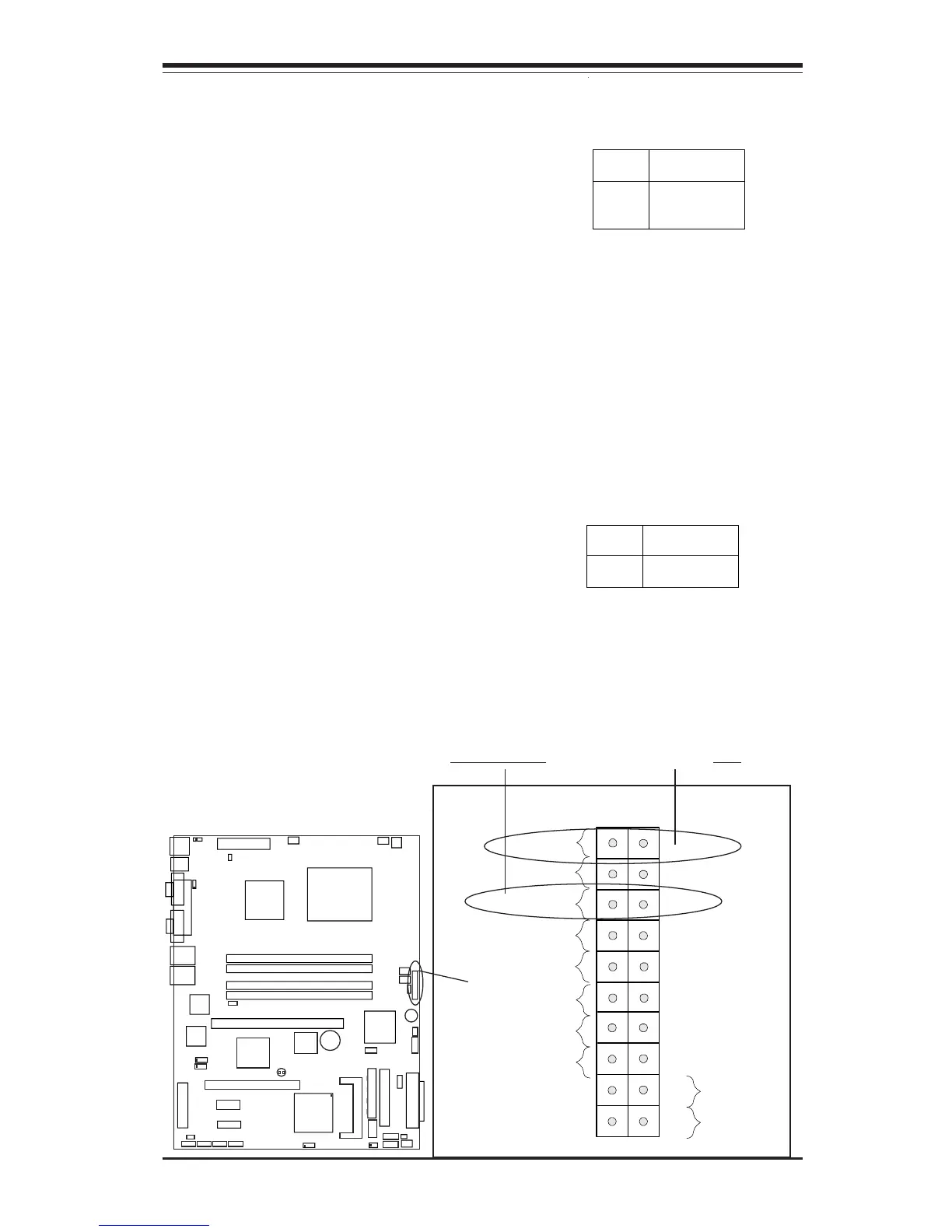
Power On_LED Connector
The Power LED connector is lo-
cated on pins 15, 16 of JF1. (*Use
JLED for a 3-pin connector.) This
connection is used to provide LED
indication of power being supplied
to the system. See the table on
the right for pin definitions.
Pin
Number
15
16
Definition
+5V
Ground
Power_LED
Pin Definitions (JF1)
NMI Button
The non-maskable interrupt button
header is located on pins 19 and
20 of JF1. Refer to the table on
the right for pin definitions.
Pin
Number
19
20
Definition
Control
Ground
NMI Button Pin
Definitions (JF1)
NIC1 LED
Power Butto