2-10
P8SC8/P8SCi User's Manual
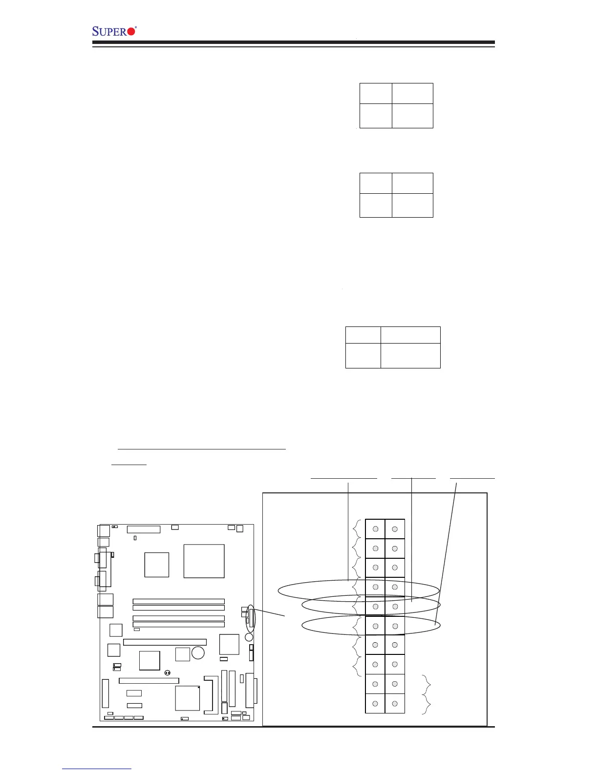
*IDE/SATA (*See the note
below)
The IDE/SATA LED is located on
pins 13, 14 of JF1. This connects
to the hard drive LED to display all
IDE and SATA activities. See the
table on the right for pin defini-
tions.
(*Note: This LED is for all IDE and SATA
devices)
Pin
Number
13
14
Definition
+5V
HD Active
IDE
Pin Definitions (JF1)
NIC1/NIC2 LED Indicators
The NIC (Network Interface Con-
troller) LED connection for GLAN
port1 is located on pins 11 and 12
of JF1 and the LED connection for
GLAN Port2 is on Pins 9 and 10.
Attach the NIC LED cables to dis-
play network activity. Refer to the
table on the right for pin defini-
tions.
NIC1 LED Pin
Definitions
(JF1)
Pin
Number
11
12
Definition
Vcc
GND
NIC2 LED Pin
Definitions
(JF1)
Pin
Number
9
10
Definition
Vcc
GND
NIC1 LED
Power Butto