Chapter 1: Introduction
1-3
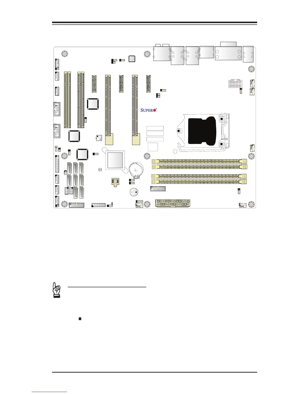
X10SAE Motherboard Layout
Important Notes to the User
•See Chapter 2 for detailed information on jumpers, I/O ports and JF1 front
panel connections.
•" " indicates the location of "Pin 1".
•Jumpers not indicated are for testing only.
•When LED1 (Onboard Power LED Indicator) is on, system power is on. Un-
plug the power cable before installing or removing any components.
1394 CODE
JLED1
JVR2
JPL1
JBR1
JPL2
JPAC1
JPME2
JWD1
JPI1
JVR1
JBT1
LV33
JSTBY1
JSD1
T-SGPIO1
X10SAE
Rev. 1.01
BIOS
LICENSE
JTPM1
JPW2
I-SATA1
I-SATA2
I-SATA3
I-SATA5
I-SATA4
J1394_2
J1394_1
JL1
JHD_AC1
JWOR1
JSPDIF_OUT
JI2C1
JI2C2
JPW1
MAC CODE
BAR CODE
LED1
SP1
FAN3
FAN2
FAN5
FAN1FAN4
JD1
SLOT5 PCI-E 2.0 X1
SLOT3 PCI-E 2.0 X1
SLOT1 PCI 33MHz
SLOT2 PCI 33MHz
USB 14/15(3.0)
USB12/13(3.0)
USB8/9
USB 2/3
LAN2 LAN1
HDMI/DP
KB/MOUSE
CPU
/CPU FAN
USB 0/1
AUDIO FP
DIMMB1
DIMMB2
HD AUDIO
USB4/5
USB6/7
DIMMA1
DIMMA2
JF1
Always populate blue sockets first;
Unbuffered ECC/Non-ECC DDR3 DIMM required
SLOT4 PCI-E 3.0 X8 (IN X16)
SLOT6 PCI-E 3.0 X16
SLOT7 PCI-E 2.0 X1
COM2
COM1
VGA/DVI
USB10/11(3.0)
T-SGPIO2
A-SATA0
A-SATA1
BIOS
Intel PCH
I-SATA0