2-26
X10SAE User’s Manual
1394 CODE
JLED1
JVR2
JPL1
JBR1
JPL2
JPAC1
JPME2
JWD1
JPI1
JVR1
JBT1
LV33
JSTBY1
JSD1
T-SGPIO1
X10SAE
Rev. 1.01
BIOS
LICENSE
JTPM1
JPW2
I-SATA1
I-SATA2
I-SATA3
I-SATA5
I-SATA4
J1394_2
J1394_1
JL1
JHD_AC1
JWOR1
JSPDIF_OUT
JI2C1
JI2C2
JPW1
MAC CODE
BAR CODE
LED1
SP1
FAN3
FAN2
FAN5
FAN1FAN4
JD1
SLOT5 PCI-E 2.0 X1
SLOT3 PCI-E 2.0 X1
SLOT1 PCI 33MHz
SLOT2 PCI 33MHz
USB 14/15(3.0)
USB12/13(3.0)
USB8/9
USB 2/3
LAN2 LAN1
HDMI/DP
KB/MOUSE
CPU
/CPU FAN
USB 0/1
AUDIO FP
DIMMB1
DIMMB2
HD AUDIO
USB4/5
USB6/7
DIMMA1
DIMMA2
JF1
Always populate blue sockets first;
Unbuffered ECC/Non-ECC DDR3 DIMM required
SLOT4 PCI-E 3.0 X8 (IN X16)
SLOT6 PCI-E 3.0 X16
SLOT7 PCI-E 2.0 X1
COM2
COM1
VGA/DVI
USB10/11(3.0)
T-SGPIO2
A-SATA0
A-SATA1
BIOS
Intel PCH
I-SATA0
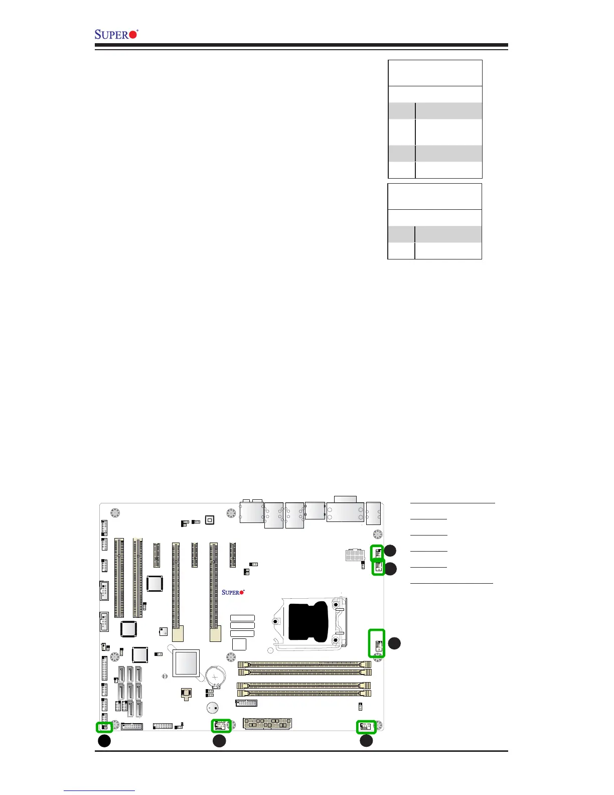
Fan Header
Pin Denitions
Pin# Denition
1 Ground (Black)
2 2.5A/+12V
(Red)
3 Tachometer
4 PWM_Control
Fan Headers (Fan 1 ~ Fan 5)
The X10SAE has ve fan headers (Fan 1~Fan
5). These fans are 4-pin fan headers. Although
pins 1-3 of the fan headers are backward
compatible with the traditional 3-pin fans, we
recommend the use 4-pin fans to take advan-
tage of the fan speed control via Pulse Width
Modulation through BIOS. This allows the fan
speeds to be automatically adjusted based on
the motherboard temperature. Refer to the table
on the right for pin denitions.
A
B
A. Fan 1 (CPU Fan)
B. Fan 2
C. Fan 3
D. Fan 4
E. Fan 5
F. Chassis Intrusion
C
D
E
Chassis Intrusion (JL1)
A Chassis Intrusion header is located at JL1 on
the motherboard. Attach the appropriate cable
from the chassis to inform you of a chassis intru-
sion when the chassis is opened.
Chassis Intrusion
Pin Denitions (JL1)
Pin# Denition
1 Intrusion Input
2 Ground