Chapter 1: Introduction
1-5
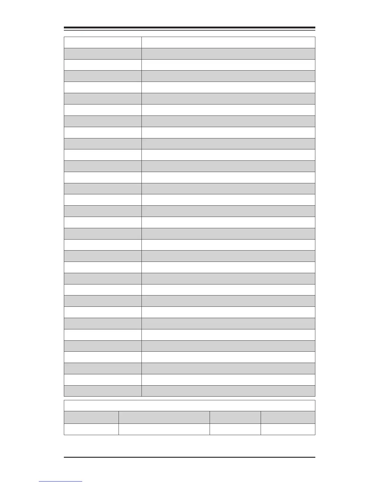
HD AUDIO High-Denition Audio Connectors (on the I/O back panel)
Battery Onboard Battery
COM1/COM2 COM1/COM2 Port Headers
Fan1~Fan5 System/CPU Fan Headers (Fan1: CPU Fan)
HDMI/DP Backplane HDMI(High-Denition Multimedia Interface)/DP Audio Port
JD1 Speaker/buzzer (Pins 3-4: Buzzer, Pins 1~4: External Speaker)
JF1 Front Panel Control Header
JL1 Chassis Intrusion Header
JLED1 Power LED Indicator Header
JPW1 24-pin ATX Main Power Connector (Required)
JPW2 +12V 8-pin CPU power Connector (Required)
JSD1 SATA DOM (Device_On_Module) Power Connector
JSPDIF_OUT Sony/Philips Digital Interface (SPDIF)_Out Header
JSTBY1 Standby Power Header
JTPM1 Trusted Platform Module/Port 80 Connector
JVR1/JVR2 PWM SMB programming headers 1/2(for debugging only)
JWOR1 Wake_On-Ring Header
KB/Mouse Keyboard/Mouse Connectors
LAN1/LAN2 Gigabit (RJ45) Ports (LAN1/2)
SP1 Internal Speaker/Buzzer
A-SATA0/A-SATA1 (ASMedia) Serial ATA (SATA 3.0) Ports 0/1 (6Gb/sec)
I-SATA0-I-SATA5 (Intel) Serial ATA (SATA 3.0) Ports 0-5 (6Gb/sec)
Slot 3/Slot 5/Slot 7 PCI-Express 2.0 x1 Slots
Slot 6 PCI-Express 3.0 x16 Slot
Slot 4 PCI-Express 3.0 x8 in x16 Slot
Slot 1, Slot 2 PCI 33MHz Slot (5V)
T-SGPIO 1/2 Serial_Link General Purpose I/O Connection Headers 1/2
USB 0/1, 2/3 Backpanel USB 2.0 Ports 0/1, 2/3
USB 10/11 Backpanel USB 3.0 Ports 10/11
USB 4/5, USB 6/7, USB 8/9 Front Panel Accessible USB 2.0 Headers 4/5, 6/7, 8/9
USB 3.0 12/13, 14/15 Front Panel Accessible USB 3.0 Headers 12/13, 14/15
VGA/DVI Backpanel VGA/DVI (Digital Video Interface) Port
X10SAE LED Indicators
LED Description Color/State Status
LED1 Onboard Standby PWR LED Green: Solid on Power On