1-4
X8DTH-6/X8DTH-6F/X8DTH-i/X8DTH-iF User's Manual
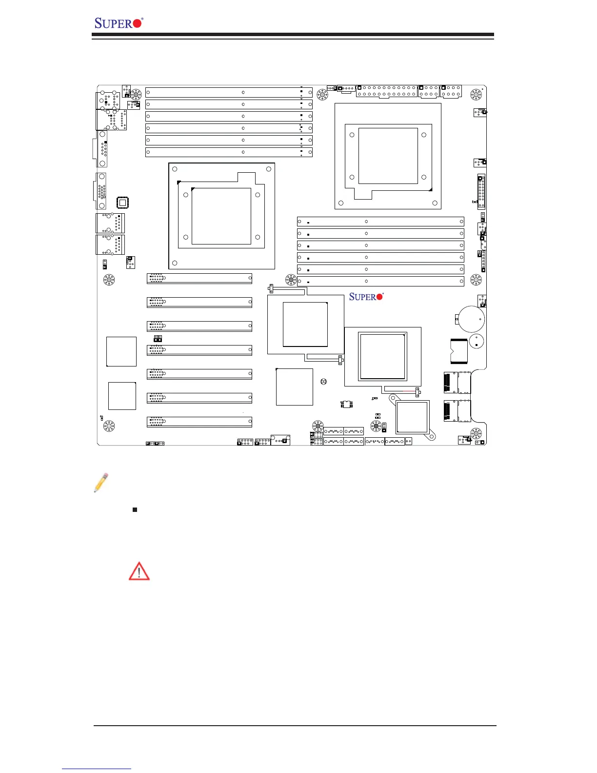
Jumpers not indicated are for test purposes only. 1.
" " indicates the location of Pin 1.2.
When DP4 is on, the onboard power connection is on. Make sure to unplug 3.
the power cables before removing or installing components.
Warning! 1. To prevent damage to the power supply or motherboard,
please use a power supply that contains a 24-pin and two 8-pin power
connectors. Be sure to connect these connectors to the 24-pin (JPW1)
and the two 8-pin (JPW2,JPW3) power connectors on the motherboard.
Failure in doing so will void the manufacturer warranty on your power
supply and motherboard.
2. To avoid system overheating, be sure to provide adequate air fl ow to
the system.
Notes
Quick Reference
SPI BIOS
J*
I-SATA1
I-SATA0
I-SATA5
I-SATA4
JBT1
SATA-SGPIO0
DP5
LED5
DP4
JPL1
JPG1
JPB
JPS1
JWD
JI2C2
JI2C1
JOH1
JD1
LAN1
VGA
FAN5
KB/MS
P2-DIMM3A
FAN6
P2-DIMM3B
JPI2C
JPW1
JPW2
FAN1
P2-DIMM2A
P2-DIMM2B
P2-DIMM1A
P2-DIMM1B
FAN7
COM1
CPU1
JF1
CPU2
IPMI_LAN
USB0/1
PWR_LED
P1-DIMM1B
P1-DIMM1A
FAN2
P1-DIMM2A
SMBus1
LAN2
FAN8
P1-DIMM3B
Slot7 PCI-E 2.0 X8
P1-DIMM3A
FAN3
Slot6 PCI-E 2.0 X8
Slot5 PCI-E 2.0 X8
Battery
Slot4 PCI-E 2.0 X8
Buzzer
Slot3 PCI-E 2.0 X8
FLASH
(IOH36D-1)
BMC
Slot2 PCI-E 2.0 X8
SAS Activity
SAS0~3
ICH10R
SAS4~7
Slot1 PCI-E 2.0 X8
USB4/5
USB3
USB6/7
LSI
SAS2008
FAN4
JPW3
P1-DIMM2B
LAN CTRL
SAS
PHY
I-SATA2
I-SATA3
X8DTH
Rev. 1.01
SATA-SGPIO1
DP6
DP7
Intel
(South Bridge)
5520
Intel
(IOH36D-2)
5520
Intel
RAID Key
JL1
J7