Chapter 2: Installation
2-27
SPI BIOS
J*
I-SATA1
I-SATA0
I-SATA5
I-SATA4
JBT1
SATA-SGPIO0
DP5
LED5
DP4
JPL1
JPG1
JPB
JPS1
JWD
JI2C2
JI2C1
JOH1
JD1
LAN1
VGA
FAN5
KB/MS
P2-DIMM3A
FAN6
P2-DIMM3B
JPI2C
JPW1
JPW2
FAN1
P2-DIMM2A
P2-DIMM2B
P2-DIMM1A
P2-DIMM1B
FAN7
COM1
CPU1
JF1
CPU2
IPMI_LAN
USB0/1
PWR_LED
P1-DIMM1B
P1-DIMM1A
FAN2
P1-DIMM2A
SMBus1
LAN2
FAN8
P1-DIMM3B
Slot7 PCI-E 2.0 X8
P1-DIMM3A
FAN3
Slot6 PCI-E 2.0 X8
Slot5 PCI-E 2.0 X8
Battery
Slot4 PCI-E 2.0 X8
Buzzer
Slot3 PCI-E 2.0 X8
FLASH
(IOH36D-1)
BMC
Slot2 PCI-E 2.0 X8
SAS Activity
SAS0~3
ICH10R
SAS4~7
Slot1 PCI-E 2.0 X8
USB4/5
USB3
USB6/7
LSI
SAS2008
FAN4
JPW3
P1-DIMM2B
LAN CTRL
SAS
PHY
I-SATA2
I-SATA3
X8DTH
Rev. 1.01
SATA-SGPIO1
DP6
DP7
Intel
(South Bridge)
5520
Intel
(IOH36D-2)
5520
Intel
RAID Key
JL1
J7
A
A. JI
2
C1
B. JI
2
C2
C. VGA Enable
B
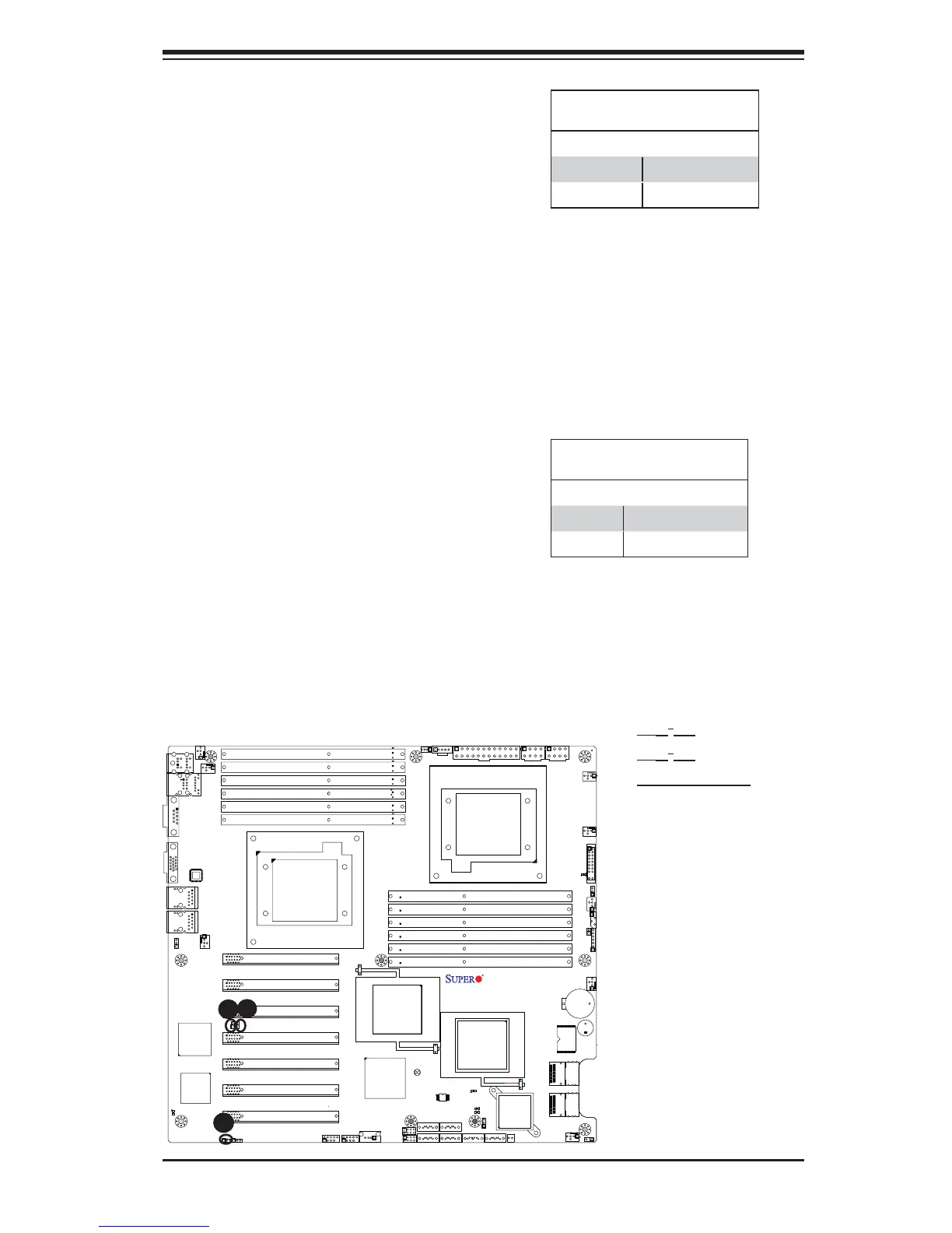
I
2
C Bus to PCI-Exp. Slots
Use Jumpers JI
2
C1 and JI
2
C2 to connect
the System Management Bus (I
2
C) to
PCI-Express slots in order to improve
PCI slot performance. These two jump-
ers are to be set at the same time. The
default setting is Closed to enable the
connections. See the table on the right
for jumper settings.
I
2
C for PCI-E slots
Jumper Settings
Jumper Setting Defi nition
Closed Enabled (Default)
Open Disabled
C
VGA Enable
Jumper JPG1 allows you to enable
video connections on the motherboard.
See the table on the right for jumper
settings.
VGA Enable
Jumper Settings
Jumper Setting Defi nition
1~2 Enabled (Default)
2~3 Disabled