Chapter 2: Installation
2-25
SPI BIOS
J*
I-SATA1
I-SATA0
I-SATA5
I-SATA4
JBT1
SATA-SGPIO0
DP5
LED5
DP4
JPL1
JPG1
JPB
JPS1
JWD
JI2C2
JI2C1
JOH1
JD1
LAN1
VGA
FAN5
KB/MS
P2-DIMM3A
FAN6
P2-DIMM3B
JPI2C
JPW1
JPW2
FAN1
P2-DIMM2A
P2-DIMM2B
P2-DIMM1A
P2-DIMM1B
FAN7
COM1
CPU1
JF1
CPU2
IPMI_LAN
USB0/1
PWR_LED
P1-DIMM1B
P1-DIMM1A
FAN2
P1-DIMM2A
SMBus1
LAN2
FAN8
P1-DIMM3B
Slot7 PCI-E 2.0 X8
P1-DIMM3A
FAN3
Slot6 PCI-E 2.0 X8
Slot5 PCI-E 2.0 X8
Battery
Slot4 PCI-E 2.0 X8
Buzzer
Slot3 PCI-E 2.0 X8
FLASH
(IOH36D-1)
BMC
Slot2 PCI-E 2.0 X8
SAS Activity
SAS0~3
ICH10R
SAS4~7
Slot1 PCI-E 2.0 X8
USB4/5
USB3
USB6/7
LSI
SAS2008
FAN4
JPW3
P1-DIMM2B
LAN CTRL
SAS
PHY
I-SATA2
I-SATA3
X8DTH
Rev. 1.01
SATA-SGPIO1
DP6
DP7
Intel
(South Bridge)
5520
Intel
(IOH36D-2)
5520
Intel
RAID Key
JL1
J7
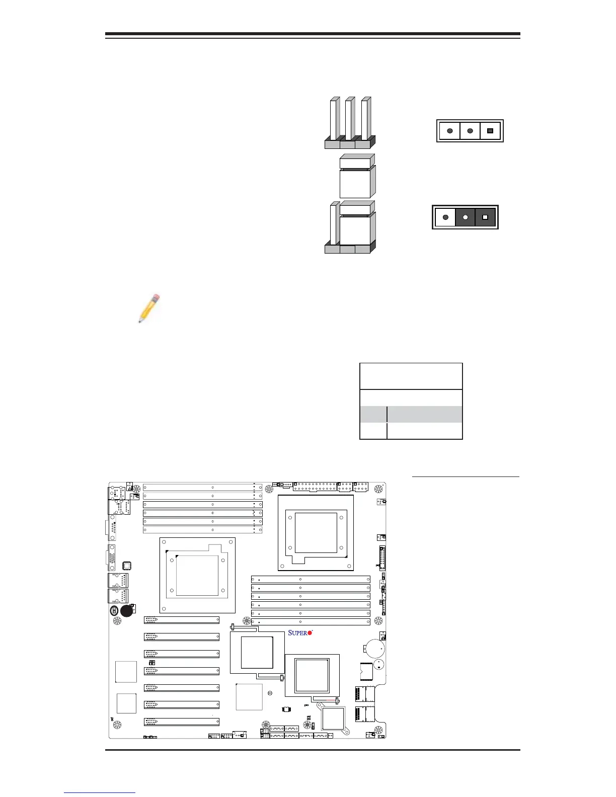
2-7 Jumper Settings
Explanation of Jumpers
To modify the operation of the mother-
board, jumpers can be used to choose
between optional settings. Jumpers cre-
ate shorts between two pins to change
the function of the connector. Pin 1
is identifi ed with a square solder pad
on the printed circuit board. See the
motherboard layout pages for jumper
locations.
Note: On two pin jumpers,
"Closed" means the jumper
is on and "Open" means the
jumper is off the pins.
Connector
Pins
Jumper
Cap
Setting
Pin 1-2 short
3 2 1
3 2 1
GLAN Enable/Disable
Use JPL1 to enable or disable GLAN
Port1/GLAN Port2 on the mother-
board. See the table on the right for
jumper settings. The default setting is
Enabled.
GLAN Enable
Jumper Settings
Pin# Defi nition
1-2 Enabled (default)
2-3 Disabled
A
A. GLAN Port 1/2 Enable