Chapter 2: Installation
2-19
X8DTH
Rev. 1.01
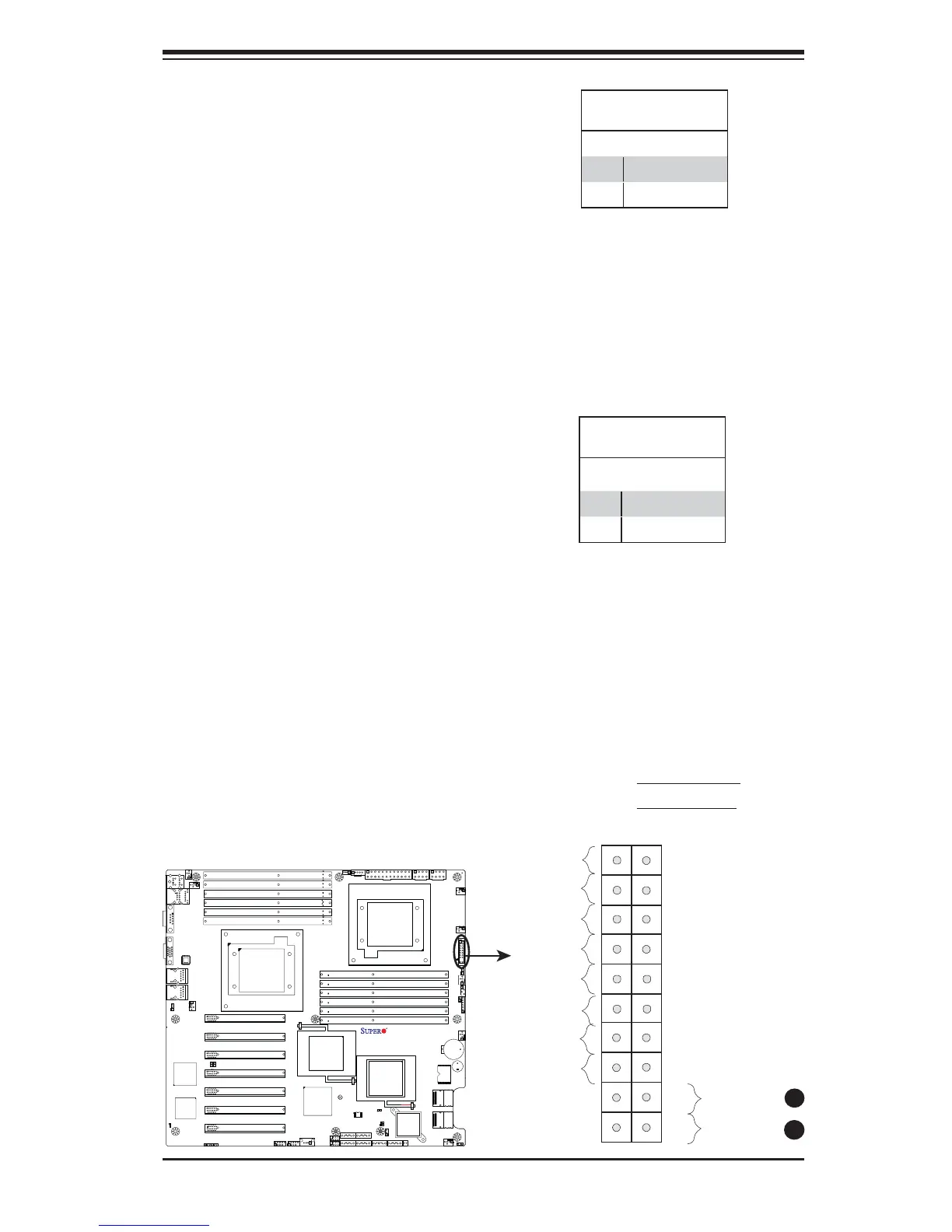
Power Button
The Power Button connection is located
on pins 1 and 2 of JF1. Momentarily con-
tacting both pins will power on/off the sys-
tem. This button can also be confi gured
to function as a suspend button (with a
setting in the BIOS - see Chapter 4). To
turn off the power when set to suspend
mode, press the button for at least 4
seconds. Refer to the table on the right
for pin defi nitions.
Power Button
Pin Defi nitions (JF1)
Pin# Defi nition
1 Signal
2 +3V Standby
Reset Button
The Reset Button connection is located
on pins 3 and 4 of JF1. Attach it to a
hardware reset switch on the computer
case. Refer to the table on the right for
pin defi nitions.
Reset Button
Pin Defi nitions (JF1)
Pin# Defi nition
3 Reset
4 Ground
A. Reset Button
B. PWR Button
A
B
Power Button
OH/Fan Fail LED
1
NIC1 LED
Reset Button
2
HDD LED
Power LED
Reset
PWR
Vcc
Vcc
Vcc
Vcc
Ground
Ground
1920
Vcc
X
Ground
NMI
X
Vcc
PWR Fail LED
NIC2 LED