2-22
X8DTH-6/X8DTH-6F/X8DTH-i/X8DTH-iF User's Manual
SPI BIOS
J*
I-SATA1
I-SATA0
I-SATA5
I-SATA4
JBT1
SATA-SGPIO0
DP5
LED5
DP4
JPL1
JPG1
JPB
JPS1
JWD
JI2C2
JI2C1
JOH1
JD1
LAN1
VGA
FAN5
KB/MS
P2-DIMM3A
FAN6
P2-DIMM3B
JPI2C
JPW1
JPW2
FAN1
P2-DIMM2A
P2-DIMM2B
P2-DIMM1A
P2-DIMM1B
FAN7
COM1
CPU1
JF1
CPU2
IPMI_LAN
USB0/1
PWR_LED
P1-DIMM1B
P1-DIMM1A
FAN2
P1-DIMM2A
SMBus1
LAN2
FAN8
P1-DIMM3B
Slot7 PCI-E 2.0 X8
P1-DIMM3A
FAN3
Slot6 PCI-E 2.0 X8
Slot5 PCI-E 2.0 X8
Battery
Slot4 PCI-E 2.0 X8
Buzzer
Slot3 PCI-E 2.0 X8
FLASH
(IOH36D-1)
BMC
Slot2 PCI-E 2.0 X8
SAS Activity
SAS0~3
ICH10R
SAS4~7
Slot1 PCI-E 2.0 X8
USB4/5
USB3
USB6/7
LSI
SAS2008
FAN4
JPW3
P1-DIMM2B
LAN CTRL
SAS
PHY
I-SATA2
I-SATA3
X8DTH
Rev. 1.01
SATA-SGPIO1
DP6
DP7
Intel
(South Bridge)
5520
Intel
(IOH36D-2)
5520
Intel
RAID Key
JL1
J7
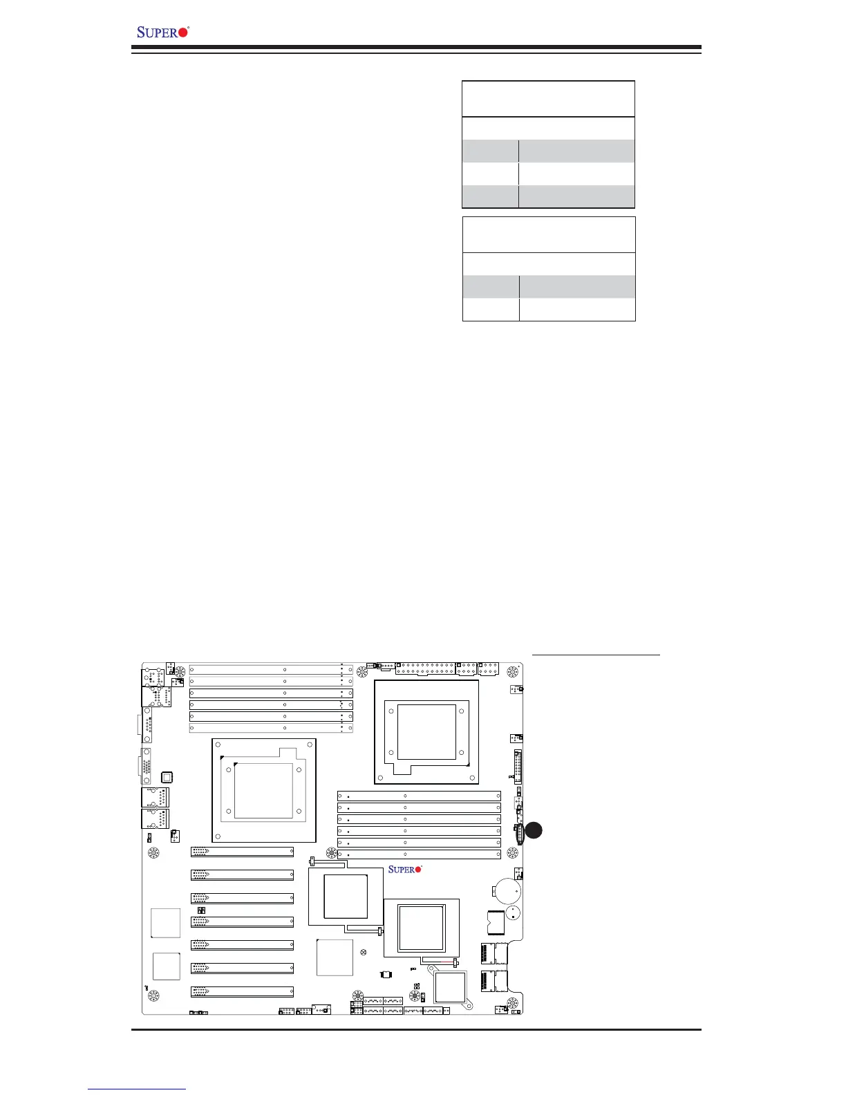
A
A. PWR LED/Speaker
Power LED/Speaker
On the JD1 header, pins 1-3 are used
for power LED indication, and pins 4-7
are for the speaker. See the tables
on the right for pin defi nitions. Please
note that the speaker connector pins
(4-7) are for use with an external
speaker. If you wish to use the on-
board speaker, you should close pins
6-7 with a jumper.
Speaker Connector
Pin Defi nitions
Pin Setting Defi nition
Pins 4-7 External Speaker
Pins 6-7 Internal Speaker
PWR LED Connector
Pin Defi nitions
Pin Setting Defi nition
Pin 1 Anode (+)
Pin2 Cathode (-)
Pin3 NA