JRK1
LE1
JWF1
SP1
JIPMB1
JPME1
BT1
JBT1
JP3
JWD
JPB1
JL1
JF1
FAN3
FAN2
FAN1
FANB
JTPM1
JPWR1
JPWR2
JI2C1
X9DR3/i-F
SCU4~7
SCU0~3
P2 DIMMH2
P2 DIMMG2
P2 DIMMH1
P2 DIMMG1
P2 DIMME1
P2 DIMME2
P2 DIMMF1
P2 DIMMF2
P1 DIMMA2
P1 DIMMA1
P1 DIMMB2
P1 DIMMB1
P1 DIMMD2
P1 DIMMD1
P1 DIMMC1
P1 DIMMC2
USB4/5
LAN2
TPM/PORT80
USB10/11
USB8/9
USB6
IPMI_LAN
ALWAYS POPULAT E DIMMxA FIRST
I-SATA5
I-SATA4
I-SATA3
I-SATA2
I-SATA1
VGA
COM1
KB/Mouse
I-SATA0
T-SGPIO2
T-SGPIO1
COM2
JSTBY1
FAN4
USB 0/1
LAN1
PHY
LAN
CTRL
BMC
CTRL
SIO
BIOS
JPWR3
Rev. 1.11a
Battery
PCH
C602/
C606
USB 2/3
JPL1
J29
DM1
JD1
JOH1
J21
JITP0
JPG1
J22
JPME2
JI2C1JI2C2
CPU1
CPU2
CPU2 Slot5 PCI-E 3.0 x 8
CPU2 Slot 6 PCI-E 3.0 x 16
CPU1 Slot1 PCI-E 3.0 x 8
CPU2 Slot4 PCI-E 3.0 x 16
CPU1 Slot3 PCI-E 3.0 x 8
CPU1 Slot2 PCI-E 3.0 x 16
FAN6 FAN5
FANA
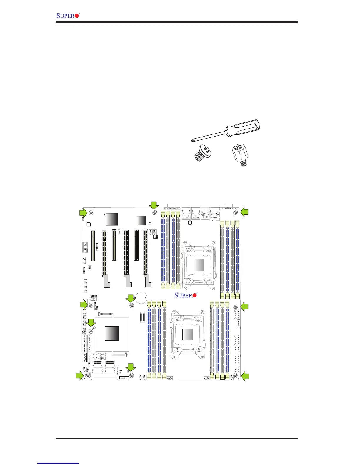
2-5 Motherboard Installation
All motherboards have standard mounting holes to t different types of chassis.
Make sure that the locations of all the mounting holes for both motherboard and
chassis match. Although a chassis may have both plastic and metal mounting fas-
teners, metal ones are highly recommended because they ground the motherboard
to the chassis. Make sure that the metal standoffs click in or are screwed in tightly.
Then use a screwdriver to secure the motherboard onto the motherboard tray.
Tools Needed
•Phillips Screwdriver
•Pan head screws (10 pieces)
•Standoffs (10 pieces, if needed)
Location of Mounting Holes
There are ten (10) mounting holes on this motherboard indicated by the arrows.
Caution: 1) To avoid damaging the motherboard and its components,
please do not use a force greater than 8 lb/inch on each mounting screw
during motherboard installation. 2) Some components are very close to the
mounting holes. Please take precautionary measures to prevent damage
to these components when installing the motherboard to the chassis.

 Loading...


