JRK1
LE1
JWF1
SP1
JIPMB1
JPME1
BT1
JBT1
JP3
JWD
JPB1
JL1
JF1
FAN3
FAN2
FAN1
FANB
JTPM1
JPWR1
JPWR2
JI2C1
X9DR3/i-F
SCU4~7
SCU0~3
P2 DIMMH2
P2 DIMMG2
P2 DIMMH1
P2 DIMMG1
P2 DIMME1
P2 DIMME2
P2 DIMMF1
P2 DIMMF2
P1 DIMMA2
P1 DIMMA1
P1 DIMMB2
P1 DIMMB1
P1 DIMMD2
P1 DIMMD1
P1 DIMMC1
P1 DIMMC2
USB4/5
LAN2
TPM/PORT80
USB10/11
USB8/9
USB6
IPMI_LAN
ALWAYS POPULATE DIMMxA FIRST
I-SATA5
I-SATA4
I-SATA3
I-SATA2
I-SATA1
VGA
COM1
KB/Mouse
I-SATA0
T-SGPIO2
T-SGPIO1
COM2
JSTBY1
FAN4
USB 0/1
LAN1
PHY
LAN
CTRL
BMC
CTRL
SIO
BIOS
JPWR3
Rev. 1.11a
Battery
PCH
C602/
C606
USB 2/3
JPL1
J29
DM1
JD1
JOH1
J21
JITP0
JPG1
J22
JPME2
JI2C1JI2C2
CPU1
CPU2
CPU2 Slot5 PCI-E 3.0 x 8
CPU2 Slot 6 PCI-E 3.0 x 16
CPU1 Slot1 PCI-E 3.0 x 8
CPU2 Slot4 PCI-E 3.0 x 16
CPU1 Slot3 PCI-E 3.0 x 8
CPU1 Slot2 PCI-E 3.0 x 16
FAN6 FAN5
FANA
Power Button
OH/Fan Fail LED
1
NIC1 LED
Reset Button
2
HDD LED
Power LED
Reset
PWR
Vcc
Vcc
Vcc
Vcc
Ground
Ground
1920
Vcc
X
Ground
NMI
X
Vcc
PWR Fail LED
NIC2 LED
B
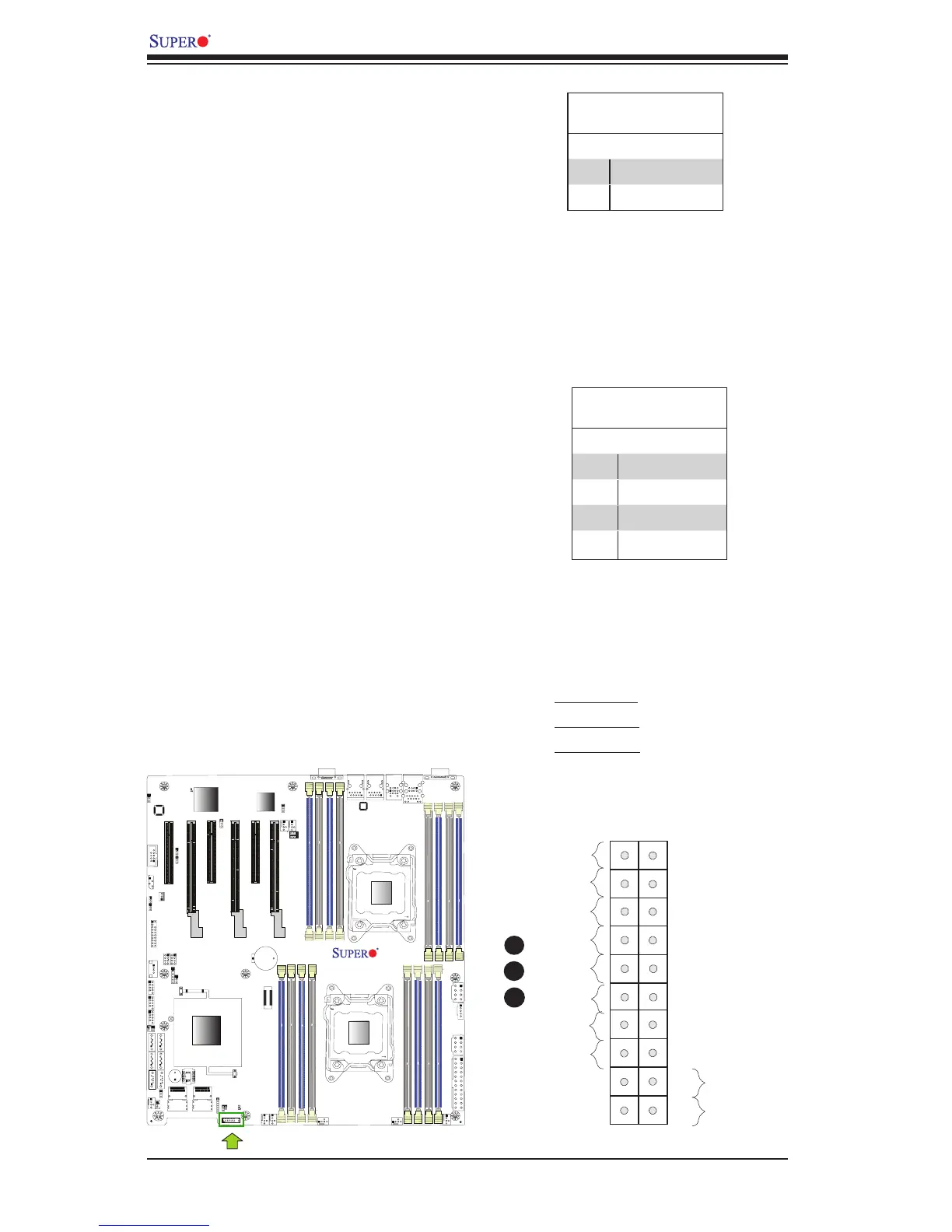
NIC1/NIC2 LED Indicators
The NIC (Network Interface Control-
ler) LED connection for GLAN port 1 is
located on pins 11 and 12 of JF1, and
the LED connection for GLAN Port 2 is
on Pins 9 and 10. Attach the NIC LED
cables here to display network activity.
Refer to the table on the right for pin
denitions.
HDD LED
The HDD LED connection is located
on pins 13 and 14 of JF1. Attach a
cable here to indicate HDD activ-
ity. See the table on the right for pin
denitions.
HDD LED
PinDenitions(JF1)
Pin# Denition
13 3.3V Standby
14 HD Active
C
A. HDD LED
B. NIC1 LED
C. NIC2 LED
A
GLAN1/2 LED
PinDenitions(JF1)
Pin# Denition
9 Vcc
10 NIC 2 LED
11 Vcc
12 NIC 1 LED

 Loading...


