JRK1
LE1
JWF1
SP1
JIPMB1
JPME1
BT1
JBT1
JP3
JWD
JPB1
JL1
JF1
FAN3
FAN2
FAN1
FANB
JTPM1
JPWR1
JPWR2
JI2C1
X9DR3/i-F
SCU4~7
SCU0~3
P2 DIMMH2
P2 DIMMG2
P2 DIMMH1
P2 DIMMG1
P2 DIMME1
P2 DIMME2
P2 DIMMF1
P2 DIMMF2
P1 DIMMA2
P1 DIMMA1
P1 DIMMB2
P1 DIMMB1
P1 DIMMD2
P1 DIMMD1
P1 DIMMC1
P1 DIMMC2
USB4/5
LAN2
TPM/PORT80
USB10/11
USB8/9
USB6
IPMI_LAN
ALWAYS POPULATE DIMMxA FIRST
I-SATA5
I-SATA4
I-SATA3
I-SATA2
I-SATA1
VGA
COM1
KB/Mouse
I-SATA0
T-SGPIO2
T-SGPIO1
COM2
JSTBY1
FAN4
USB 0/1
LAN1
PHY
LAN
CTRL
BMC
CTRL
SIO
BIOS
JPWR3
Rev. 1.11a
Battery
PCH
C602/
C606
USB 2/3
JPL1
J29
DM1
JD1
JOH1
J21
JITP0
JPG1
J22
JPME2
JI2C1JI2C2
CPU1
CPU2
CPU2 Slot5 PCI-E 3.0 x 8
CPU2 Slot 6 PCI-E 3.0 x 16
CPU1 Slot1 PCI-E 3.0 x 8
CPU2 Slot4 PCI-E 3.0 x 16
CPU1 Slot3 PCI-E 3.0 x 8
CPU1 Slot2 PCI-E 3.0 x 16
FAN6 FAN5
FANA
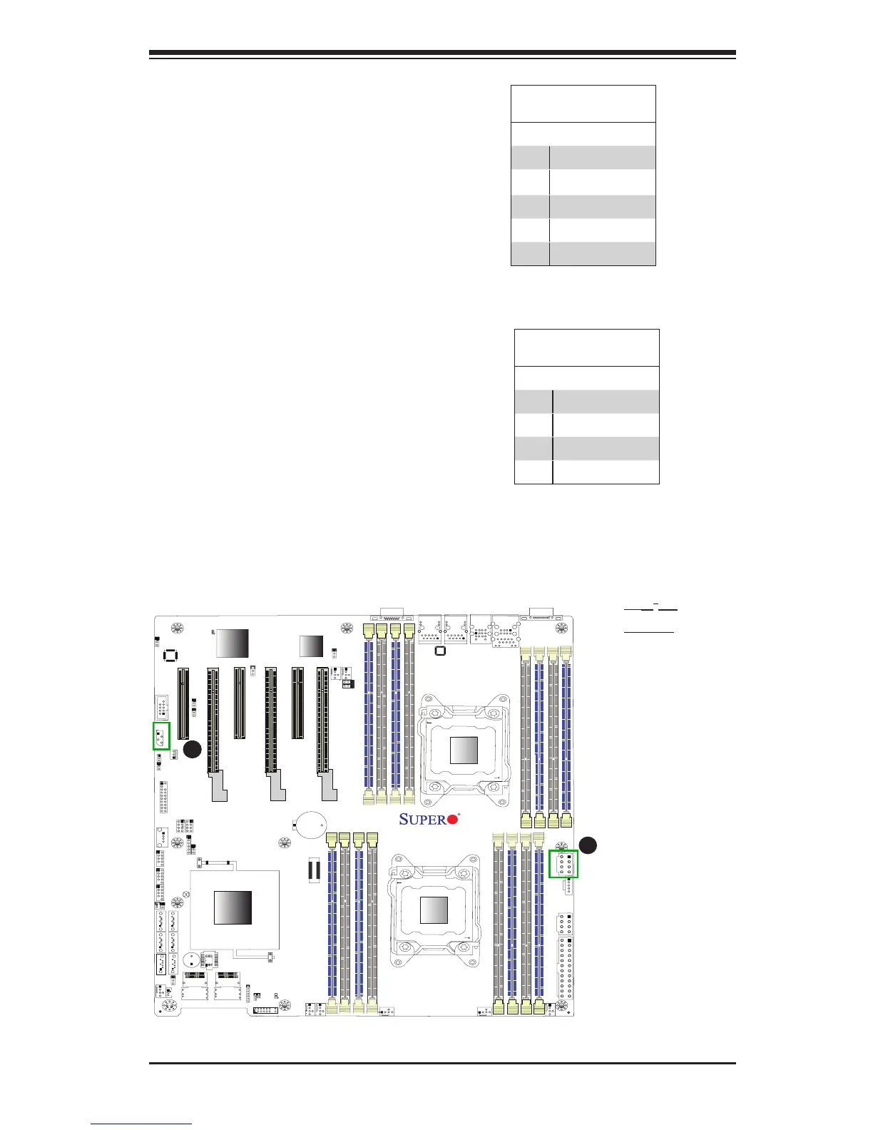
A
B
A. JI
2
C1
B. IPMB
Power SMB (I
2
C) Connector
Power System Management Bus (I
2
C)
Connector (JI
2
C1) monitors power
supply, fan and system temperatures.
See the table on the right for pin
denitions.
PWR SMB
PinDenitions
Pin# Denition
1 Clock
2 Data
3 PWR Fail
4 Ground
5 +3.3V
IPMB
A System Management Bus header
for IPMI 2.0 is located at JIPMB1.
Connect the appropriate cable here
to use the IPMB I
2
C connection on
your system.
IPMB Header
PinDenitions
Pin# Denition
1 Data
2 Ground
3 Clock
4 No Connection

 Loading...


