SP91 User Manual
23
24
25
26
27
28
29
30
31
32
33
34
35
36
Host
Printer
Printer
Printer
Host
GND
GND
GND
GND
GND
GND
GND
GND
nInit
nFault
GND
DK_STATUS
+5V
nSelectIn
GND
GND
GND
GND
GND
GND
GND
GND
nInit
nDataAvail/Data0, 4
ND
ND
ND
1284-Active
*NC: Not Connected
ND: Not Defined
NOTES : 1. A prefix “ n ” to signal names refer to low level active signals.
2. To the host provided with none of the signal lines listed above, both-way communication
fails.
3. For interfacing, signal lines shall use twisted pair cables with the return sides connected to
signal ground level.
4. Interfacing conditions shall be all based on the TTL level to meet the following characteristics
In addition, both rise and fall time of each signal shall be 0.5 μ s or less .
5. Data transmission shall not ignore the signal n Ack or Busy. An attempt to transmit data with
signal, nAck or Busy, ignored can cause data lose. (Data transmission for the printer shall be
made after verifying the nAck signal or while the Busy signal is at the low level.)
6. Interface cables shall be as min required short in length as possible.
Electrical
Electrical
Electrical
Electrical Characteristics
Characteristics
Characteristics
Characteristics
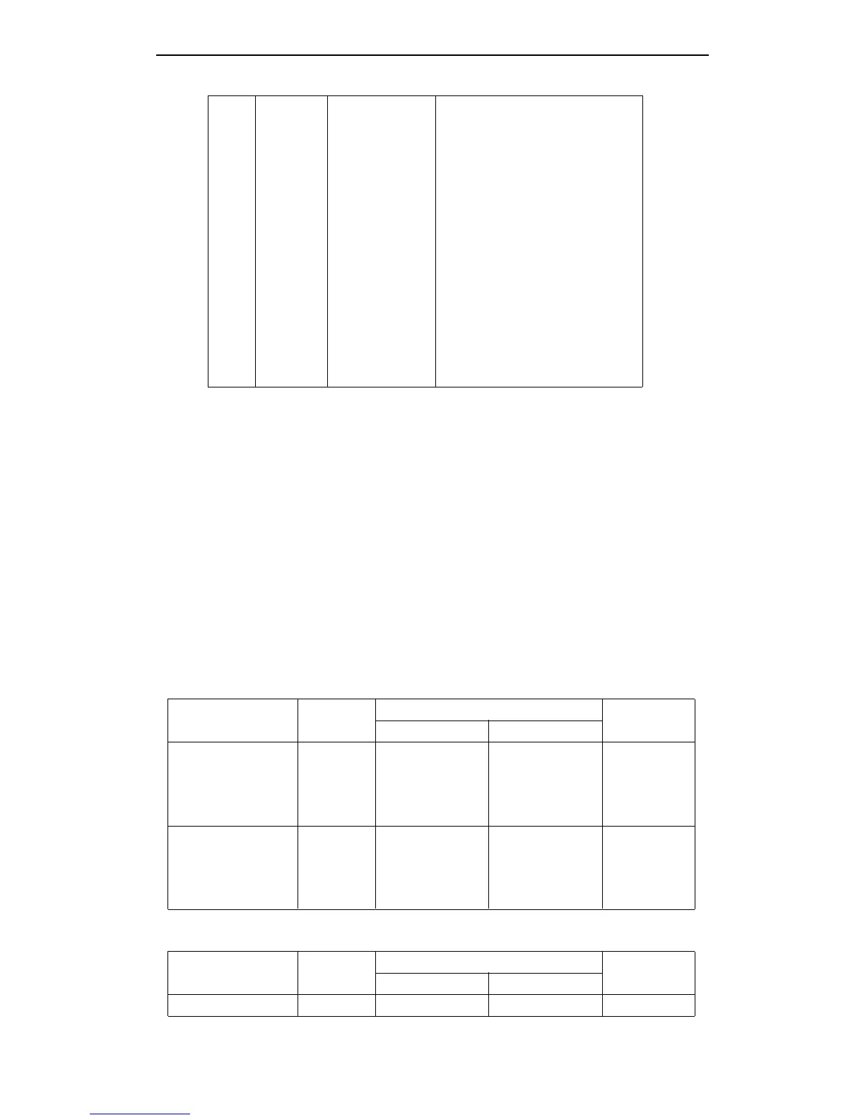
DC Characteristics (Except Logic- H, + 5 V signals)
Characteristics Symbol
Specifications
Conditions
Min Max
Output High Voltage
Output Low Voltage
Output High Current
Output Low Current
V
OH
V
OL
I
OH
I
OL
*2.4 V
-0.5 V
0.32 mA
-12 mA
5.5 V
*0.4 V
-
-
*I
OH
=0.32 mA
*I
OL
=-12 mA
V
OH
=2.4 V
V
OL
=0.4 V
Input High Voltage
Input Low Voltage
Input High Current
Input Low Current
V
IH
V
IL
I
IH
I
IL
2.0 V
-
-
-
-
0.8 V
-0.32 mA
12 mA
V
IH
=2.0 V
V
IL
=0.8 V
Logic - H Signal Sender Characteristics
Characteristics Symbol
Specifications
Conditions
Min Max
Output High Voltage V
OH
3.0 V 5.5 V While the