SP91 User Manual
using the both-way communication facility in the Nibble/Byte Modes in accordance with the IEEE
1284.
In this case, different from in the RS-232 serial interface s pecifications, the real-time interruptions
from the printer to the host are disabled and thus precautions must be taken to the followings:
1) Allowable capacity of the printer internal buffer is 99 bytes (except ASB status), The status signals
exceeding this capacity will be discarded, To prevent possible loss of status, the host shall be ready
for data acception (Reverse Mode).
2) When ASB is used, the host is preferably in the wait state for data acception (ReverseIdle
Mode).When this state is not available, the host shall enter the Reverse Mode to always monitor the
presence of data.
3) When ASB is used, preference shall be given to the ASB status for transmission over the other
status signals. Once one ASB conditions changed, all ready to send ASB conditions from last time
that need to send together, then sending the latest ASB conditions.
2.1.3
2.1.3
2.1.3
2.1.3 Ethernet
Ethernet
Ethernet
Ethernet Interface
Interface
Interface
Interface
2.1.3.
2.1.3.
2.1.3.
2.1.3. 1Interface
1Interface
1Interface
1Interface Specifications
Specifications
Specifications
Specifications
Ethernet Type: Standard Ethernet (10M)
TCP/IP agreement: ETHERNET, ARP, IP, TCMP, IGMP, UDP, TCP, HTTP, DHCP;
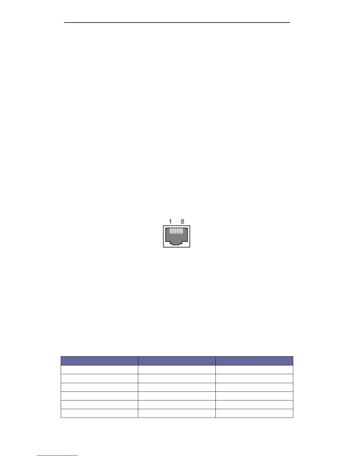
Connector Type: RJ45 (as table)
2.1.3.2
2.1.3.2
2.1.3.2
2.1.3.2 Interface
Interface
Interface
Interface connection
connection
connection
connection
1.Default IP address “ 192.168.1.6 ” , IP port “ 9100 ” , checked by self-test list;
2.Link the printer to LAN, open IE and input the IP address of the printer, default “ 192.168.1.6 ” , Carriage
return to log in. After modif y ing the related information, then “ Reset ” ;
3.
If
printing by Windows driver, install SP91 driver. After installing driver, find installed SP91 driver in
“ printer and fax ” . Choose attribute, then “ Port ” - “ Add port ” -choose “ Standard TCP/IP Port ” , operate
according its prompt.
4.Change driver to this port, test through printing test page.
Notes:
Notes:
Notes:
Notes:
1.Default IP port 9100, normal condition that needn ’ t change;
2.Add “ Standard TCP/IP Port ” , when choosing “ Device type ” , to choose “ Standard ” .
2.1.3.3
2.1.3.3
2.1.3.3
2.1.3.3 Interface
Interface
Interface
Interface Pin
Pin
Pin
Pin Signal
Signal
Signal
Signal Definition
Definition
Definition
Definition
Pin NO. Signal Name Signal Source
1 TX+ Tranceive Data+ ( Send signa +)
2 TX- Tranceive Data+ -( Send signa -)
3 RX+ Receive Data+ ( Receive signal +)
4 N/C Not connected( Blank )
5 N/C Not connected( Blank )
6 RX- Receive Data -( Receive signal -)