OPERATING PROCEDURES
14 OP CIC1200E Rev4.0 06-09 Chapter 4
4
4.3. Power Supply Stand-by
The CIC is connected to the mains but thus far not
started (rear panel of CIC: Main Power plug is con
-
nected).
The alphanumeric display of the front panel reads:
STAND BY
The processor of the CIC1200 is constantly connect-
ed to power so it monitors the crucial program steps
of the exposure lamp e.g.
• the internal clock of the CIC safety programs
preventing the premature ignition of the expo
-
sure lamp.
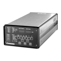
The control panel of the CIC comprises 3 annuncia-
tor groups with their LEDs (see adjacent picture of
the Control Panel)
• LAMP TYPE
• DISPLAY
• FAILURE
4.4. Selecting the Exposure
Lamp
Warning!
Selection of improper lamp parameters
causes a risk of injury for users and of
damage for the machine!
Lamps driven by wrong voltage or cur-
rent could not only become inoperable
but may explode!
Explosion would destroy optical com-
ponents and release mercury vapors.
Only lamps approved by SUSS Micro
-
Tec for use with the CIC1200 must be
installed!
Verify and ensure always:
• that the lamp type selected at the CIC
fits completely to the installed lamp
type.
• that the currently used lamp is correct-
ly installed and oriented in the lamp
house (see table 4.4 for prescribed ori
-
entation).
Table 4.4
Select the appropriate exposure lamp before start-
ing the CIC with the key ON of the front panel. The
alphanumeric display (2x4 characters) of the front
panel reads:
STAND BY
Actuate the key SET LAMP (press button for 2 sec)
to activate the menu LAMP TYPE of the CIC unit.
The alphanumeric display shows the currently load
-
ed lamp e.g.
LAMP 1000.
Lamp
Orientation
+ (Anode)
200W Hg Down
350W Hg Down
500W Hg Down
500W Hg-Xe Up
1000W Hg Down