8
mild steel and coated with a controlled thickness of hard chrome. Glass is
loaded into the groove near the tip of the puller bar and is held in position
by tightening down the clamping knob (R).
V- Bearings
(S in Figure
1-5)
These bearings are the guides for the Puller Bar motion. They are made of
stainless steel and must NEVER be oiled (see Maintenance Section). Note
that these bearings are mounted on stainless steel bushings, one of which
is round with the other two being hexagonal. The hexagonal (eccentric)
bushings are used to adjust position and ease of travel of the PULLER
BARS (see Maintenance Section). Do not adjust the eccentrics without
additional instruction.
Pull Cable
(T in Figure
1-5)
This cable transmits the pulling force of the solenoid to the Puller Bars via
the Upper (F) and Lower Pulley Assemblies. It is made of flexible metal
with a nylon coating. Never pinch or distort the cable. The cable is
terminated with crimped-on clamps or ‘swages’ at the back-end of each
Puller Bar.
Glass Stop
Mounting (U
in Figure 1-5)
Holes for mounting the glass stop. Either the left side or the right may be
used.
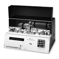
1.6 Cabinet
Baseplate The top think metal plate on which the mechanical assemblies are
mounted.
Base The Base includes the cabinet to which the top Baseplate is mounted as
well as the transformers and the circuit board contained within.
1.6.1 Electronics
The P-97 micropipette puller is controlled by a Z-80 microprocessor. Three digital-to-analog
(D-A) converters control the HEAT, PULL, and VELOCITY values. The HEAT power supply
is a precision constant current switching unit, which will vary less than 10 milliamperes with
a plus or minus 10% change in the AC line current. The PULL supply is a constant current
DC power supply. The velocity trip point is set by a D-A converter. The output of the velocity
transducer is compared to the output of the velocity D-A to determine when the trip velocity
is reached.
P-97 FLAMING/BROWN MICROPIPETTE PULLER OPERATION MANUAL – REV. 2.43 - DOM (20161118)