P-97 FLAMING/BROWN MICROPIPETTE PULLER OPERATION MANUAL – REV. 2.43 - DOM (20161118)
10
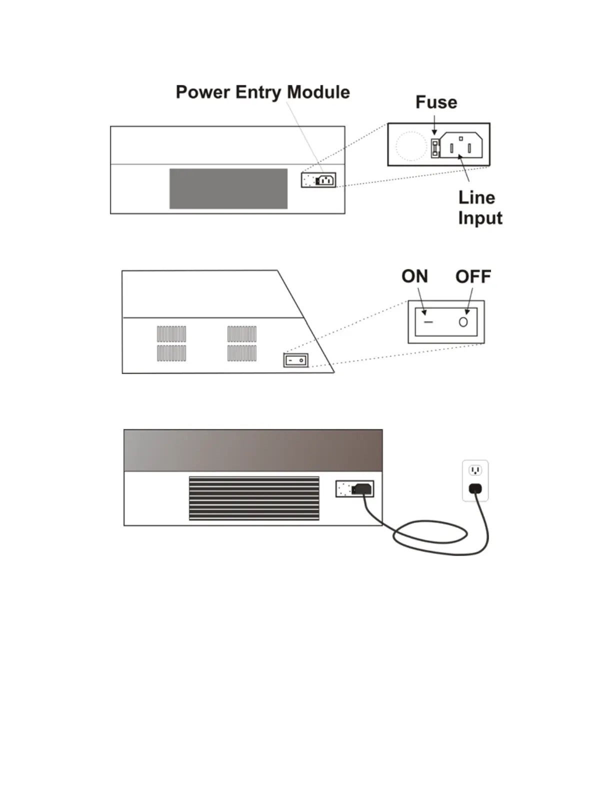
Figure 2-1. P-97 Cabinet (rear view), showing power entry module.
Make certain that the Power Switch located on the left end of the P-97 cabinet is turned OFF.
Figure 2-2. P-97 Cabinet (end view, left), showing power switch.
Plug the power cord provided with the P-97 into the Line Input socket on the Power Entry
Module and then to a power source of the appropriate voltage and frequency.
Figure 2-3. Power connection.