3
size and shape, and will almost certainly require adjustment after replacing a filament. To
make this adjustment:
1. Carefully slide the glass to be used along the V-groove in the puller bar, and see where it
is positioned relative to the filament.
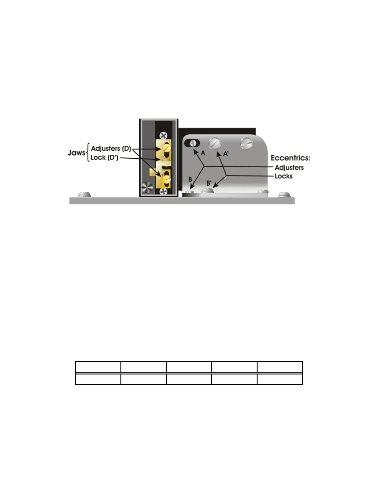
2. Locate the aluminum angle plate to the right of the filament assembly and behind the
right puller bar. Two chrome eccentric screws (A and B in Figure 4-2) in slots are
mounted on this bracket, one located on the vertical face of the bracket and one on the
horizontal face. Identify the flathead locking screws to the right of each chrome screw.
Figure 4-2. Filament alignment.
3. Loosen the locking screws (A’ and B’)
4. Turn the eccentric chrome screw (A) on the vertical face to adjust the vertical position of
the filament and the eccentric chrome screw (B) on the horizontal face to adjust the
front-to-back position of the filament.
5. Tighten the locking screws (A’ and B’).
6. If the vertical excursion available with the vertical cam screw is not enough to center the
glass, you will need to reposition the upper and lower heater jaw assemblies by first
loosening the brass screws holding the jaws to the black nylon (D). Reposition the jaws
then retighten the brass screws and re-position the air jet.
Testing the Position: After positioning the filament it is important to determine if the
filament is centered left-to-right over the air jet.
Run a RAMP TEST with your glass and the new filament. If you are unclear as to how to run
the ramp test, please review the Software Control Functions section of this manual.
Install a one-line program similar to the following:
HEAT PULL VELOCITY TIME PRESSURE
Ramp 70 70 250 500
This program is only being used to test pipette length. Pull a pair of pipettes. Remove the
pipettes from the puller bars and hold them side by side as shown in the figure below. If the
shanks of the pipettes vary in length, this is an indication that the filament is not centered
left to right relative to the air jet, thus one pipette is “seeing” more cooling than the other.
Loosen the filament clamping screws and move the filament very slightly towards the side
P-97 FLAMING/BROWN MICROPIPETTE PULLER OPERATION MANUAL – REV. 2.43 - DOM (20161118)