P-97 FLAMING/BROWN MICROPIPETTE PULLER OPERATION MANUAL – REV. 2.43 - DOM (20161118)
32
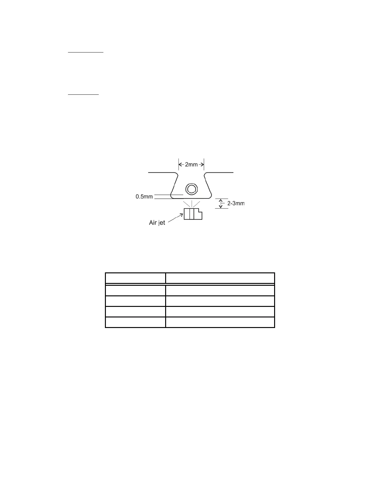
3.6.4.1 Positioning
When using the trough filaments, the glass tubing should be positioned just above the bottom
of the filament (approx. 0.5mm), and centered between the two sides (Figure 3-15). See
section Error! Reference source not found. for adjustments and alignment.
3.6.4.2 Geometry
The geometry of the trough filament is an important factor for proper heat application to the
glass. Replacement trough filaments should have a profile similar to that illustrated in
Figure 3-15, where the distance between the top corners (distance A) is approximately 2/3 the
length of the bottom of the filament. This geometry will provide improved heat distribution
to the top of the glass tubing. When replacing a filament, check the new filament geometry. If
it differs appreciably from the ideal, you can easily modify it by grasping the bottom corners
with non-serrated forceps and gently pushing on the horizontal ‘wings’.
Figure 3-16. Trough filament positioning.
The trough filament you select depends upon the length of the taper that you want. Wider
filaments for special purposes are available upon request.
Table 3-5. Trough filament sizes.
Filament Description
FT315B 1.5mm wide trough
FT320B 2mm wide trough
FT330B (standard) 3mm wide trough
FT345B 4.5mm wide trough