Do you have a question about the Sutter Instrument P-1000 and is the answer not in the manual?
Essential safety guidelines for operating the P-1000 micropipette puller.
Safety guidelines for electrical operation of the P-1000.
Precautions to prevent electrical shock and fire hazards.
Recommendations to prevent back injury when moving the instrument.
Safety precautions during instrument operation.
Safety guidelines for handling produced micropipettes.
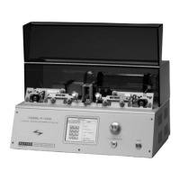
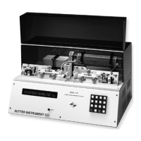
Overview of the P-1000 Micropipette Puller and its capabilities.
Specifications for glass tubing and heating filaments.
Specifications for glass tubing compatible with the P-1000.
Information on selecting appropriate heating filaments.
Contact information and support services provided by Sutter Instrument.
Description of the P-1000's front panel components and interface.
Detailed mechanical description and terminology of the P-1000.
Basic mechanical description and terminology of the P-1000.
Components and function of the air cooling system.
Components of the heating assembly.
Guides cables from solenoid to puller bars.
Description of the instrument's cabinet and baseplate.
Description of the microprocessor control and power supplies.
Initial screen displayed upon powering up, includes system check.
Main screen for program selection and navigation.
Procedure for selecting and opening a program.
Steps to recalibrate the touchscreen display.
Steps and procedures for pulling a pipette.
Summary of the pull results displayed after a pull.
Accessing detailed results of recent pulls.
Procedure for establishing optimal heat settings.
Accessing various system options and program settings.
Setting the system clock for program timestamping.
Protecting a program from editing or deletion.
Enabling Thermolock mode for consistent pulling conditions.
Duration of dry air purge before pulling.
Duration of dry air purge after pulling.
Displaying and managing stored programs.
Searching and installing pre-designed programs.
Modifying existing programs and creating new ones.
Procedures for installing new or existing programs.
Specific program types for patch pipette fabrication.
Programs for microinjection and high resistance electrodes.
Managing program lock status.
Preventing filament damage by monitoring heat settings.
Explanation of cooling modes for pipette pulling.
Monitoring and managing jaw temperature for stability.
Adding or editing notes for programs.
Common error messages and their solutions.
Contents of the P-1000 shipping box and unpacking instructions.
Steps for setting up the P-1000.
Connecting the P-1000 to the power source.
Initial setup and operation guide for new users.
Essential steps for immediate operation of the P-1000.
Standard factory settings for the P-1000.
Information on creating, managing, and using programs.
How programs are organized into lines and cycles.
Detailed explanation of HEAT, PULL, VELOCITY, TIME, DELAY, PRESSURE.
Step-by-step description of a typical pull cycle.
System testing and screen display upon startup.
How to modify existing programs.
Tips for editing program parameters effectively.
Adding or editing notes for programs.
Overview of the main menu options.
General navigation of the menu screen.
Accessing system-wide settings.
Accessing program-specific settings.
Procedure for establishing optimal heat settings.
Recommended starting and maximum HEAT values.
Step-by-step guide to pulling pipettes.
Detailed steps for pulling a pipette.
Overview of parameter adjustments for different pipette types.
General information on parameter adjustments.
Parameter adjustments for micropipette fabrication.
Effect of HEAT on pipette length and tip size.
Effect of PULL strength on tip diameter and taper.
Determining the point where heat turns off.
Cooling mode using TIME parameter.
Cooling mode using DELAY parameter.
Adjusting cooling air pressure.
Impact of filament width on tip length.
Parameter adjustments for patch pipette fabrication.
HEAT settings for patch pipette fabrication.
PULL strength for patch pipettes.
VELOCITY for patch pipette tip formation.
Cooling parameters for patch pipettes.
PRESSURE settings for patch pipettes.
Using Thermolock for stable pulling.
Guide to programming patch pipettes.
Tips for optimizing micropipette pulling.
Adjusting pull time for sharp pipettes.
Adjusting length and tip size.
Routine cleaning procedures for the P-1000.
Step-by-step guide to replacing the heating filament.
Detailed instructions for filament replacement.
Correct positioning of the air jet relative to the filament.
Aligning the filament with the glass capillary.
How to adjust pulley tension for reproducibility.
Process for regenerating Drierite desiccant.
Steps to remove the Drierite canister.
Procedure for replacing Drierite granules.
Steps to reinstall the Drierite canister.
Addressing issues with pipette tip formation.
Guidance on selecting appropriate glass types.
Troubleshooting low pipette resistance.
Methods for achieving smaller pipette tips.
Increasing patch pipette size.
Ensuring consistent patch pipette size.
Tips for creating injection pipettes with short tapers.
Troubleshooting bent electrodes.
Addressing unequal electrode lengths.
Troubleshooting inconsistent pipette shape and resistance.
Troubleshooting general system and function issues.
Solutions for problems occurring during startup.
Common operational issues and their causes.
Interpreting emergency reset messages.
Error messages during edit or pull operations.
Using built-in diagnostics for testing hardware subsystems.
Diagnostic tests for the air pressure system.
Diagnostic tests for the heating system.
Diagnostic tests for the pull mechanism.
Diagnostic tests for the velocity sensor.
Procedure for calibrating the touchscreen.
Contact information for technical assistance.
| Type | Micropipette Puller |
|---|---|
| Temperature Control | Digital |
| Velocity Sensing | Yes |
| Number of Programs | Up to 10 |
| Weight | 5 kg |
| Pipette Type | Glass |
| Accuracy | ± 1% |
| Precision | ± 0.5% |
| Autoclavable | Yes |
| Applications | Electrophysiology, Microinjection |
| Power Supply | 110-240V, 50/60Hz |