75
6.3.1.6 Test for air leaks
The air leak test consists of raising the pressure to 500 and then turning off the
pump for 10 seconds while testing for a drop in pressure. During the 10 seconds that
the pump is turned off, an error will be reported if the pressure drops more than 6
units.
6.3.1.7 Trace and correct leaks
This sequence of tests facilitates the detection and location of leaks in the air system,
and provides guidelines on how to repair the leaks. Follow the instructions on the
screen.
Tip: A good test for full flow through the air valve and air jet is as follows:
1. Set Pressure to 500.
2. Turn on both Automatic Pressure and Open the Air Valve.
3. The Pressure transducer reading should be 450 –500.
If the pressure is significantly lower than 450, the pump is weak and could affect the
performance of your programs.
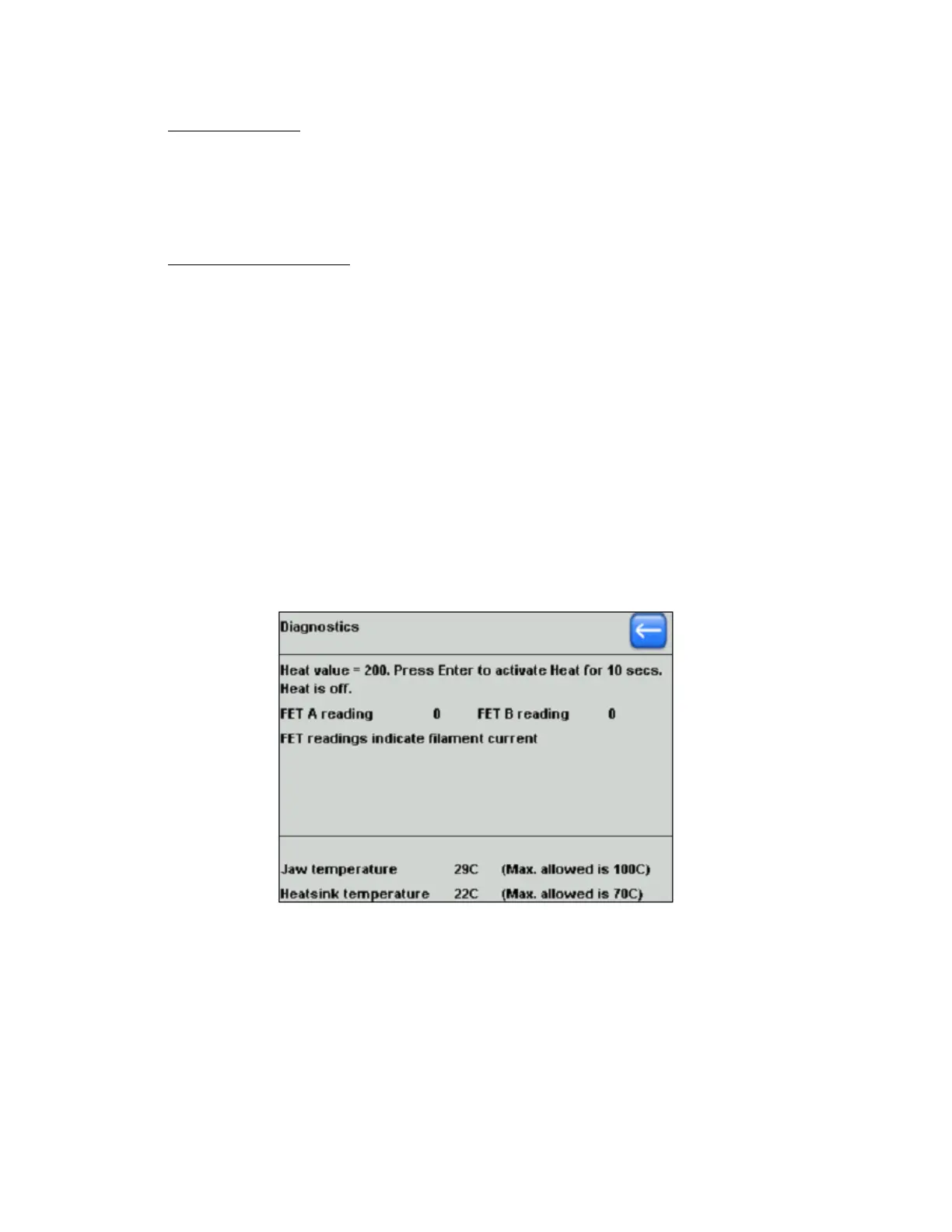
6.3.2 Heat Diagnostics
The diagnostics for the heating system is reached by the pressing Heat in the main
diagnostics screen, whereupon the screen shown in the following figure is displayed.
Figure 6-4. Heat system diagnostics screen.
To start the heat diagnostics, press Enter. The heating system is tested at a value of
200 for 10 seconds. The Heat current is controlled by two field effect transistors
(FETs). FET A and FET B currents should both be equal to the Heat value of 200,
within a few units. If they are unequal, there is circuit board fault. If they are both
lower than the Heat setting, the Heat current is low. This can be due to a circuit
board fault, but more often indicates a broken heat filament.
Fault conditions are reported in red after the test, as shown in the following figure.
P-1000 FLAMING/BROWN MICROPIPETTE PULLER SYSTEM OPERATION MANUAL – REV. 3.02 (20161118)